HD64F3694FY Renesas Electronics America, HD64F3694FY Datasheet - Page 79
HD64F3694FY
Manufacturer Part Number
HD64F3694FY
Description
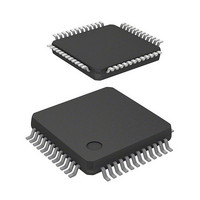
IC H8 MCU FLASH 32K 48-LQFP
Manufacturer
Renesas Electronics America
Series
H8® H8/300H Tinyr
Datasheet
1.HD64F3694GFYV.pdf
(452 pages)
Specifications of HD64F3694FY
Core Processor
H8/300H
Core Size
16-Bit
Speed
20MHz
Connectivity
I²C, SCI
Peripherals
PWM, WDT
Number Of I /o
29
Program Memory Size
32KB (32K x 8)
Program Memory Type
FLASH
Ram Size
2K x 8
Voltage - Supply (vcc/vdd)
3 V ~ 5.5 V
Data Converters
A/D 8x10b
Oscillator Type
Internal
Operating Temperature
-20°C ~ 75°C
Package / Case
48-LQFP
Lead Free Status / RoHS Status
Contains lead / RoHS non-compliant
Eeprom Size
-
Available stocks
Company
Part Number
Manufacturer
Quantity
Price

Part Number:
HD64F3694FYJV
Manufacturer:
RENESAS/瑞萨
Quantity:
20 000
Company:
Part Number:
HD64F3694FYV
Manufacturer:
Renesas Electronics America
Quantity:
10 000


Exception handling may be caused by a reset, a trap instruction (TRAPA), or interrupts.
A reset has the highest exception priority. Exception handling starts as soon as the reset is cleared
by the RES pin. The chip is also reset when the watchdog timer overflows, and exception handling
starts. Exception handling is the same as exception handling by the RES pin.
Exception handling starts when a trap instruction (TRAPA) is executed. The TRAPA instruction
generates a vector address corresponding to a vector number from 0 to 3, as specified in the
instruction code. Exception handling can be executed at all times in the program execution state,
regardless of the setting of the I bit in CCR.
External interrupts other than NMI and internal interrupts other than address break are masked by
the I bit in CCR, and kept masked while the I bit is set to 1. Exception handling starts when the
current instruction or exception handling ends, if an interrupt request has been issued.
3.1
Table 3.1 shows the vector addresses and priority of each exception handling. When more than
one interrupt is requested, handling is performed from the interrupt with the highest priority.
Table 3.1
Relative Module
RES pin
Watchdog timer
External interrupt
pin
CPU
Address break
Reset
Trap Instruction
Interrupts
Exception Sources and Vector Address
Exception Sources and Vector Address
Exception Sources
Reset
Reserved for system use
NMI
Trap instruction (#0)
Break conditions satisfied
Section 3 Exception Handling
(#1)
(#2)
(#3)
Vector
Number
0
1 to 6
7
8
9
10
11
12
Rev.5.00 Nov. 02, 2005 Page 49 of 418
Vector Address
H'0000 to H'0001
H'0002 to H'000D
H'000E to H'000F
H'0010 to H'0011
H'0012 to H'0013
H'0014 to H'0015
H'0016 to H'0017
H'0018 to H'0019
Section 3 Exception Handling
REJ09B0028-0500
Priority
High
Low
Related parts for HD64F3694FY
Image
Part Number
Description
Manufacturer
Datasheet
Request
R

Part Number:
Description:
(HD64 Series) Hitachi Single-Chip Microcomputer
Manufacturer:
Hitachi Semiconductor
Datasheet:

Part Number:
Description:
KIT STARTER FOR M16C/29
Manufacturer:
Renesas Electronics America
Datasheet:

Part Number:
Description:
KIT STARTER FOR R8C/2D
Manufacturer:
Renesas Electronics America
Datasheet:

Part Number:
Description:
R0K33062P STARTER KIT
Manufacturer:
Renesas Electronics America
Datasheet:

Part Number:
Description:
KIT STARTER FOR R8C/23 E8A
Manufacturer:
Renesas Electronics America
Datasheet:

Part Number:
Description:
KIT STARTER FOR R8C/25
Manufacturer:
Renesas Electronics America
Datasheet:

Part Number:
Description:
KIT STARTER H8S2456 SHARPE DSPLY
Manufacturer:
Renesas Electronics America
Datasheet:

Part Number:
Description:
KIT STARTER FOR R8C38C
Manufacturer:
Renesas Electronics America
Datasheet:

Part Number:
Description:
KIT STARTER FOR R8C35C
Manufacturer:
Renesas Electronics America
Datasheet:

Part Number:
Description:
KIT STARTER FOR R8CL3AC+LCD APPS
Manufacturer:
Renesas Electronics America
Datasheet:
Part Number:
Description:
KIT STARTER FOR RX610
Manufacturer:
Renesas Electronics America
Datasheet:

Part Number:
Description:
KIT STARTER FOR R32C/118
Manufacturer:
Renesas Electronics America
Datasheet:

Part Number:
Description:
KIT DEV RSK-R8C/26-29
Manufacturer:
Renesas Electronics America
Datasheet:

Part Number:
Description:
KIT STARTER FOR SH7124
Manufacturer:
Renesas Electronics America
Datasheet:

Part Number:
Description:
KIT STARTER FOR H8SX/1622
Manufacturer:
Renesas Electronics America
Datasheet: