TLE4270 Infineon Technologies, TLE4270 Datasheet - Page 9
TLE4270
Manufacturer Part Number
TLE4270
Description
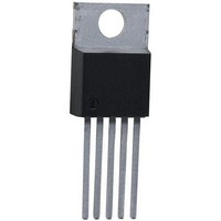
IC REGULATOR LDO 5V TO220-5
Manufacturer
Infineon Technologies
Datasheet
1.TLE4270D.pdf
(20 pages)
Specifications of TLE4270
Regulator Topology
Positive Fixed
Voltage - Output
5V
Voltage - Input
6 ~ 42 V
Voltage - Dropout (typical)
0.35V @ 550mA
Number Of Regulators
1
Current - Output
550mA (Max)
Current - Limit (min)
650mA
Operating Temperature
-40°C ~ 150°C
Mounting Type
Through Hole
Package / Case
TO-220-5 (Bent and Staggered Leads)
Number Of Outputs
1
Polarity
Positive
Input Voltage Max
42 V
Output Voltage
5 V
Output Type
Fixed
Dropout Voltage (max)
0.7 V at 550 mA
Output Current
550 mA
Line Regulation
25 mV
Load Regulation
50 mV
Voltage Regulation Accuracy
2 %
Maximum Operating Temperature
+ 150 C
Mounting Style
Through Hole
Minimum Operating Temperature
- 40 C
Lead Free Status / RoHS Status
Contains lead / RoHS non-compliant
Other names
SP000011792
TLE4270NK
TLE4270NK
Available stocks
Company
Part Number
Manufacturer
Quantity
Price

Company:
Part Number:
TLE4270
Manufacturer:
INF
Quantity:
5 510
Company:
Part Number:
TLE4270
Manufacturer:
FSC
Quantity:
10 000
Company:
Part Number:
TLE4270-2D
Manufacturer:
INF
Quantity:
9 999
Part Number:
TLE4270-2D
Manufacturer:
INFINEON/英飞凌
Quantity:
20 000
Part Number:
TLE4270-2G
Manufacturer:
INFINEON/英飞凌
Quantity:
20 000
Part Number:
TLE4270-2S
Manufacturer:
INFINEON/英飞凌
Quantity:
20 000
Part Number:
TLE4270D
Manufacturer:
INFINEON/英飞凌
Quantity:
20 000
Part Number:
TLE4270G
Manufacturer:
INFINAON
Quantity:
20 000


Design Notes for External Components
An input capacitor
circuit consisting of lead inductance and input capacitance can be damped by a resistor
of approx. 1 Ω in series with
the regulating circuit. Stability is guaranteed at values of
< 3 Ω.
Reset Circuitry
If the output voltage decreases below 4.5 V, an external capacitor
discharged by the reset generator. If the voltage on this capacitor drops below
reset signal is generated on pin 2 (RO), i.e. reset output is set low. If the output voltage
rises above the reset threshold,
power-on-reset time the voltage on the capacitor reaches
be set high again. The value of the power-on-reset time can be set within a wide range
depending of the capacitance of
Reset Timing
The power-on reset delay time is defined by the charging time of an external capacitor
C
C
Definitions:
•
•
•
•
V
t
The reset reaction time
LOW after the output voltage has dropped below the reset threshold. It is typically 1 µs
for delay capacitor of 47 nF. For other values for
using the following equation:
t
Data Sheet
rd
rr
DU
D
D
≈ 20 s/F ×
= ∆
which can be calculated as follows:
= (∆
C
∆
I
∆
D,c
= upper reset timing threshold at
t
V
D
V
= reset delay time
= delay capacitors
=
= charge current, typical 14 µA
t
×
×
V
C
DU
I
D,c
D
, typical 1.8 V
/
C
I
)/∆
D,c
D
V
C
I
is necessary for compensation of line influences. The resonant
t
t
rr
rd
is the time it takes the voltage regulator to set the reset out
C
I
. An output capacitor
C
C
D
.
D
C
will be charged with constant current. After the
D
for reset delay time
9
C
D
the reaction time can be estimated
C
Q
is necessary for the stability of
V
C
DU
Q
≥ 22 µF and an ESR of
and the reset output will
C
D
Rev. 1.6, 2005-08-09
on pin 4 (D) will be
TLE 4270
V
DL
(1)
(2)
(3)
, a
Related parts for TLE4270
Image
Part Number
Description
Manufacturer
Datasheet
Request
R

Part Number:
Description:
Manufacturer:
Infineon Technologies AG
Datasheet:
Part Number:
Description:
Manufacturer:
Infineon Technologies AG
Datasheet:
Part Number:
Description:
Manufacturer:
Infineon Technologies AG
Datasheet:
Part Number:
Description:
Manufacturer:
Infineon Technologies AG
Datasheet:
Part Number:
Description:
Manufacturer:
Infineon Technologies AG
Datasheet:
Part Number:
Description:
Manufacturer:
Infineon Technologies AG
Datasheet:
Part Number:
Description:
Manufacturer:
Infineon Technologies AG
Datasheet:
Part Number:
Description:
16-bit microcontroller with 2x2 KByte RAM
Manufacturer:
Infineon Technologies AG
Datasheet:
Part Number:
Description:
NPN silicon RF transistor
Manufacturer:
Infineon Technologies AG
Datasheet:
Part Number:
Description:
NPN silicon RF transistor
Manufacturer:
Infineon Technologies AG
Datasheet:
Part Number:
Description:
NPN silicon RF transistor
Manufacturer:
Infineon Technologies AG
Datasheet:
Part Number:
Description:
NPN silicon RF transistor
Manufacturer:
Infineon Technologies AG
Datasheet:
Part Number:
Description:
Si-MMIC-amplifier in SIEGET 25-technologie
Manufacturer:
Infineon Technologies AG
Datasheet:
Part Number:
Description:
IGBT Power Module
Manufacturer:
Infineon Technologies AG
Datasheet:
Part Number:
Description:
IC for switching-mode power supplies
Manufacturer:
Infineon Technologies AG
Datasheet: