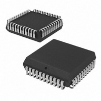
SC16C750IA44,512 NXP Semiconductors, SC16C750IA44,512 Datasheet - Page 43

SC16C750IA44,512
Manufacturer Part Number
SC16C750IA44,512
Description
IC UART 64BYTE 44PLCC
Manufacturer
NXP Semiconductors
Datasheet
1.SC16C750IA44529.pdf
(45 pages)
Specifications of SC16C750IA44,512
Number Of Channels
1, UART
Fifo's
64 Byte
Voltage - Supply
2.5V, 3.3V, 5V
With Auto Flow Control
Yes
With False Start Bit Detection
Yes
With Modem Control
Yes
With Cmos
Yes
Mounting Type
Surface Mount
Package / Case
44-PLCC
Voltage
2.25 V ~ 5.5 V
Transmit Fifo
64Byte
Receive Fifo
64Byte
Transmitter And Receiver Fifo Counter
Yes
Package Type
PLCC
Operating Supply Voltage (max)
5.5V
Mounting
Surface Mount
Pin Count
44
Operating Temperature (min)
-40C
Operating Temperature (max)
85C
Operating Temperature Classification
Industrial
Lead Free Status / RoHS Status
Lead free / RoHS Compliant
Features
-
Lead Free Status / Rohs Status
Compliant
Other names
935270053512
SC16C750IA44
SC16C750IA44
SC16C750IA44
SC16C750IA44
Available stocks
Company
Part Number
Manufacturer
Quantity
Price
Company:
Part Number:
SC16C750IA44,512
Manufacturer:
NXP Semiconductors
Quantity:
10 000
Philips Semiconductors
13. Revision history
Table 28:
9397 750 11623
Product data
Rev Date
04
03
02
01
20030620
20030314
20021211
20020904
Revision history
CPCN
-
-
-
-
[3]
[4]
[5]
[6]
[7]
Description
Product data (9397 750 11623); ECN 853-2367 30035 of 16 June 2003.
Modifications:
Product data (9397 750 11203); ECN 853-2367 29619 of 07 March 2003.
Product data (9397 750 10797); ECN 853-2367 29261 of 06 December 2002.
Product data (9397 750 10149); ECN 853-2367 28865 of 04 September 2002.
•
These transparent plastic packages are extremely sensitive to reflow soldering conditions and must
on no account be processed through more than one soldering cycle or subjected to infrared reflow
soldering with peak temperature exceeding 217 C
oven. The package body peak temperature must be kept as low as possible.
These packages are not suitable for wave soldering. On versions with the heatsink on the bottom
side, the solder cannot penetrate between the printed-circuit board and the heatsink. On versions with
the heatsink on the top side, the solder might be deposited on the heatsink surface.
If wave soldering is considered, then the package must be placed at a 45 angle to the solder wave
direction. The package footprint must incorporate solder thieves downstream and at the side corners.
Wave soldering is suitable for LQFP, QFP and TQFP packages with a pitch (e) larger than 0.8 mm; it
is definitely not suitable for packages with a pitch (e) equal to or smaller than 0.65 mm.
Wave soldering is suitable for SSOP and TSSOP packages with a pitch (e) equal to or larger than
0.65 mm; it is definitely not suitable for packages with a pitch (e) equal to or smaller than 0.5 mm.
Figure 4 “Crystal oscillator connection.” on page
added connection with resistor.
Rev. 04 — 20 June 2003
10 C measured in the atmosphere of the reflow
12: changed capacitors’ values and
© Koninklijke Philips Electronics N.V. 2003. All rights reserved.
UART with 64-byte FIFO
SC16C750
43 of 45


