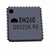
EM260-RTR Ember, EM260-RTR Datasheet - Page 15

EM260-RTR
Manufacturer Part Number
EM260-RTR
Description
IC ZIGBEE SYSTEM-ON-CHIP 40-QFN
Manufacturer
Ember
Specifications of EM260-RTR
Frequency
2.4GHz
Data Rate - Maximum
250kbps
Modulation Or Protocol
802.15.4
Applications
ZigBee™
Power - Output
-32dBm ~ 3dBm
Sensitivity
-97dBm
Voltage - Supply
2.1 V ~ 3.6 V
Current - Receiving
30mA
Current - Transmitting
34mA
Data Interface
PCB, Surface Mount
Antenna Connector
PCB, Surface Mount
Operating Temperature
-40°C ~ 85°C
Package / Case
40-QFN
For Use With
636-1009 - PROGRAMMER USB FLASH EM250/260
Lead Free Status / RoHS Status
Lead free / RoHS Compliant
Memory Size
-
Other names
636-1007-2
EM260-RTR
EM260-RTR
Available stocks
Company
Part Number
Manufacturer
Quantity
Price
4 Functional Description
4.1
4.2
Receive (RX) Path
Transmit (TX) Path
The EM260 connects to a Host microcontroller through a standard SPI interface. The Ember ZigBee Serial
Protocol (EZSP) has been defined to allow an Application to be written on the Host microcontroller of choice.
Therefore, the EM260 comes with a license to EmberZNet, the Ember ZigBee-compliant software stack. The
following brief description of the hardware modules provides the necessary background on the operation of
the EM260. For more information, contact www.ember.com/support.
The EM260 RX path spans the analog and digital domains. The RX architecture is based on a low-IF, super-
heterodyne receiver. It utilizes differential signal paths to minimize noise interference. The input RF signal is
mixed down to the IF frequency of 4MHz by I and Q mixers. The output of the mixers is filtered and combined
prior to being sampled by a 12Msps ADC. The RX filtering within the RX path has been designed to optimize the
co-existence of the EM260 with other 2.4GHz transceivers, such as the IEEE 802.11g and Bluetooth
4.1.1
The EM260 RX baseband (within the digital domain) implements a coherent demodulator for optimal perform-
ance. The baseband demodulates the O-QPSK signal at the chip level and synchronizes with the IEEE 802.15.4-
2003 preamble. Once a packet preamble is detected, it de-spreads the demodulated data into 4-bit symbols.
These symbols are buffered and passed to the hardware-based MAC module for filtering.
In addition, the RX baseband provides the calibration and control interface to the analog RX modules, includ-
ing the LNA, RX Baseband Filter, and modulation modules. The EmberZNet software includes calibration
algorithms which use this interface to reduce the effects of process and temperature variation.
4.1.2
The EM260 calculates the RSSI over an 8-symbol period as well as at the end of a received packet. It utilizes
the RX gain settings and the output level of the ADC within its algorithm.
The EM260 RX baseband provides support for the IEEE 802.15.4-2003 required CCA methods summarized in
Table 10. Modes 1, 2, and 3 are defined by the 802.15.4-2003 standard; Mode 0 is a proprietary mode.
The EM260 transmitter utilizes both analog circuitry and digital logic to produce the O-QPSK modulated signal.
The area-efficient TX architecture directly modulates the spread symbols prior to transmission. The differen-
tial signal paths increase noise immunity and provide a common interface for the external balun.
0
1
2
3
CCA Mode
RX Baseband
RSSI and CCA
Clear channel reports busy medium if either carrier sense OR RSSI exceeds their thresholds.
Clear channel reports busy medium if RSSI exceeds its threshold.
Clear channel reports busy medium if carrier sense exceeds its threshold.
Clear channel reports busy medium if both RSSI and carrier sense exceed their thresholds.
Mode Behavior
Table 10. CCA Mode Behavior
120-1003-000D
EM260
®
.
15


