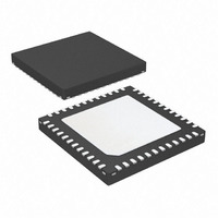
ATA5824-PLQW Atmel, ATA5824-PLQW Datasheet - Page 24

ATA5824-PLQW
Manufacturer Part Number
ATA5824-PLQW
Description
IC TXRX UHF ASK/FSK 48QFN
Manufacturer
Atmel
Datasheet
1.ATA5824-PLQW.pdf
(98 pages)
Specifications of ATA5824-PLQW
Frequency
433 ~ 435MHz; 866 ~ 870MHz
Data Rate - Maximum
20kbps
Modulation Or Protocol
ASK, FSK
Applications
RKE, TPM, Security Systems
Power - Output
10dBm
Sensitivity
-116dBm
Voltage - Supply
2.15 V ~ 3.6 V or 4.4 V ~ 5.25 V
Current - Receiving
10.5mA
Current - Transmitting
10.5mA
Data Interface
PCB, Surface Mount
Antenna Connector
PCB, Surface Mount
Operating Temperature
-40°C ~ 105°C
Package / Case
48-VQFN Exposed Pad, 48-HVQFN, 48-SQFN, 48-DHVQFN
Lead Free Status / RoHS Status
Lead free / RoHS Compliant
Memory Size
-
Available stocks
Company
Part Number
Manufacturer
Quantity
Price
Company:
Part Number:
ATA5824-PLQW
Manufacturer:
ATMEL
Quantity:
3 500
Part Number:
ATA5824-PLQW
Manufacturer:
ATMEL/爱特梅尔
Quantity:
20 000
7.15
7.16
24
RX/TX Switch
Matching Network in TX Mode
ATA5823/ATA5824
The RX/TX switch decouples the LNA from the PA in TX mode, and directs the received power
to the LNA in RX mode. To do this, it has a low impedance to GND in TX mode and a high
impedance to GND in RX mode. The pin 38 (RX_TX2) must always be connected to GND in the
application. To design a proper RX/TX decoupling a linear simulation tool for radio frequency
design together with the measured device impedances of
page
values have to be found on board.
cuit of the switch. The principal switching operation is described here according to the
application of
.
Table 7-10.
Figure 7-13. Equivalent Circuit of the Switch
In TX mode the 20 mm long and 0.4 mm wide transmission line which is much shorter than /4 is
approximately switched in parallel to the capacitor C
C
antenna with pin RF_OUT, L
capacitor as discussed later). The transmission line can be approximated with a 16 nH inductor
in series with a 1.5 resistor, the closed switch can be approximated according to
with the series connection of 1.6 nH and 5 in this mode. To have a parallel resonant high
impedance circuit with little RF power going into it looking, from the loop antenna into the trans-
mission line a capacitor of about 7.6 pF to GND is needed at the beginning of the transmission
line (this capacitor is later absorbed into C
tion). To keep the 50 impedance in RX mode at the end of this transmission line C
also about 7.6 pF. This reduces the TX power by about 0.5 dB at 433.92 MHz compared to the
case where the LNA path is completely disconnected.
8
and C
22,
433.92
868.3
Frequency
315
Table 7-10 on page 24
9
has an impedance of about 50 looking from the transmission line into the loop
MHz
MHz
Figure 3-1 on page
MHz
Impedance of the RX/TX Switch RX_TX2 Shorted to GND
2
, C
and
10
Z(RX_TX1) TX mode
6. The application of
Figure 7-13 on page 24
, C
2.5 pF
Table 7-11 on page 25
(4.8 + j3.2)
(4.5 + j4.3)
8
11
(5 + j9)
and C
9
RX_TX1
, which is then higher as needed for 50 transforma-
1.6 nH
9
connected (using a C
TX
9
to GND. The antenna connection between
Figure 4-1 on page 7
5
shows an approximate equivalent cir-
Table 7-1 on page
should be used. The exact element
Z(RX_TX1) RX mode
9
without the added 7.6 pF
(11.3 – j214)
(10.3 – j153)
(8.9 – j73)
works similarly.
11,
4829D–RKE–06/06
Table 7-7 on
Table 7-10
7
has to be


