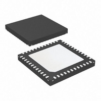
ATA5824-PLQW Atmel, ATA5824-PLQW Datasheet - Page 43

ATA5824-PLQW
Manufacturer Part Number
ATA5824-PLQW
Description
IC TXRX UHF ASK/FSK 48QFN
Manufacturer
Atmel
Datasheet
1.ATA5824-PLQW.pdf
(98 pages)
Specifications of ATA5824-PLQW
Frequency
433 ~ 435MHz; 866 ~ 870MHz
Data Rate - Maximum
20kbps
Modulation Or Protocol
ASK, FSK
Applications
RKE, TPM, Security Systems
Power - Output
10dBm
Sensitivity
-116dBm
Voltage - Supply
2.15 V ~ 3.6 V or 4.4 V ~ 5.25 V
Current - Receiving
10.5mA
Current - Transmitting
10.5mA
Data Interface
PCB, Surface Mount
Antenna Connector
PCB, Surface Mount
Operating Temperature
-40°C ~ 105°C
Package / Case
48-VQFN Exposed Pad, 48-HVQFN, 48-SQFN, 48-DHVQFN
Lead Free Status / RoHS Status
Lead free / RoHS Compliant
Memory Size
-
Available stocks
Company
Part Number
Manufacturer
Quantity
Price
Company:
Part Number:
ATA5824-PLQW
Manufacturer:
ATMEL
Quantity:
3 500
Part Number:
ATA5824-PLQW
Manufacturer:
ATMEL/爱特梅尔
Quantity:
20 000
12.3.9
4829D–RKE–06/06
Status Register (ADR 16)
Table 12-25. Control Register 8 (Function of Bit 4, Bit 3, Bit 2, Bit 1, Bit 0)
Normally the SETPWR resistor at pin 19 is used in full-duplex mode to decrease the output
power until the level at RF_IN is low enough for reception of signals (PWSELECT = 0). With
PWSELECT = 1 this resistor can also be used in normal half-duplex TX operation to adjust the
output power for production tolerances.
The status register indicates the current status of the transceiver and is readable via the 4-wire
serial interface. Setting Power_On or an event on N_Power_On is indicated by an IRQ.
Reading the status register resets the bits Power_On, DVCC_RST and the IRQ.
Table 12-26. Status Register
PWSET4
N_Power_On
DVCC_RST
Status Bit
Power_On
2
0
0
1
1
1
.
.
4
PWSET3
2
0
0
0
1
1
.
.
Function
Status of pin N_PWR_On
Pin N_PWR_ON = 0
Pin N_PWR_ON = 1
(Figure 12-3 on page
Indicates that the transceiver was woken up by pin PWR_ON (rising edge on
pin PWR_ON). During Power_On = 1, the bit CLK_ON in control register 3 is
set to 1
DVCC_RST is set to 1 if the supply voltage of the RAM (V
information in the RAM may be lost.
DVCC_RST = 0
DVCC_RST = 1
If the transceiver changes from OFF mode to IDLE mode, DVCC_RST will be set to 1.
Reading the Status register resets DVCC_RST to 0.
3
(Figure 12-4 on page
PWSET2
2
0
0
0
1
1
.
.
2
supply voltage of the RAM ok
supply voltage of the RAM was too low (typically V
45)
PWSET1
N_Power_On = 0
N_Power_On = 1
2
0
0
0
1
1
.
.
1
46).
PWSET0
2
0
1
0
0
1
.
.
0
ATA5823/ATA5824
resistor to reduce the output power
SETPWR = 800
(SETPWR: Programmable internal
Function (TX Mode, FD Mode)
SETPWR = 800
in FD and TX mode)
DVCC
3
3
16 (default)
k
) was too low and the
k
PWSET
(typically)
30
31
(typically)
0
1
+
+
(31 – PWSET)
DVCC
(31 – 16)
< 1.6V)
43


