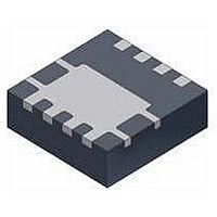
FDMC2514SDC Fairchild Semiconductor, FDMC2514SDC Datasheet - Page 3

FDMC2514SDC
Manufacturer Part Number
FDMC2514SDC
Description
MOSFET Power 25V NChan Dual Cool PowerTrench SyncFET
Manufacturer
Fairchild Semiconductor
Datasheet
1.FDMC2514SDC.pdf
(9 pages)
Specifications of FDMC2514SDC
Gate Charge Qg
31 nC
Minimum Operating Temperature
- 55 C
Configuration
Dual
Transistor Polarity
N-Channel
Resistance Drain-source Rds (on)
3.6 mOhms
Forward Transconductance Gfs (max / Min)
122 S
Drain-source Breakdown Voltage
25 V
Gate-source Breakdown Voltage
20 V
Continuous Drain Current
24 A
Power Dissipation
3 W
Maximum Operating Temperature
+ 150 C
Mounting Style
SMD/SMT
Package / Case
Power 33
Lead Free Status / RoHS Status
Lead free / RoHS Compliant
Available stocks
Company
Part Number
Manufacturer
Quantity
Price
Part Number:
FDMC2514SDC
Manufacturer:
0N
Quantity:
20 000
©2010 Fairchild Semiconductor Corporation
FDMC2514SDC Rev.C2
Thermal Characteristics
NOTES:
1. R
2. Pulse Test: Pulse Width < 300 μs, Duty cycle < 2.0%.
3. E
4. As an N-ch device, the negative Vgs rating is for low duty cycle pulse ocurrence only. No continuous rating is implied.
5. I
R
R
R
R
R
R
R
R
R
R
R
R
R
R
by the user's board design.
θJC
θJC
θJA
θJA
θJA
θJA
θJA
θJA
θJA
θJA
θJA
θJA
θJA
θJA
SD
AS
θJA
c. Still air, 20.9x10.4x12.7mm Aluminum Heat Sink, 1 in
d. Still air, 20.9x10.4x12.7mm Aluminum Heat Sink, minimum pad of 2 oz copper
e. Still air, 45.2x41.4x11.7mm Aavid Thermalloy Part # 10-L41B-11 Heat Sink, 1 in
f. Still air, 45.2x41.4x11.7mm Aavid Thermalloy Part # 10-L41B-11 Heat Sink, minimum pad of 2 oz copper
g. 200FPM Airflow, No Heat Sink,1 in
h. 200FPM Airflow, No Heat Sink, minimum pad of 2 oz copper
i. 200FPM Airflow, 20.9x10.4x12.7mm Aluminum Heat Sink, 1 in
j. 200FPM Airflow, 20.9x10.4x12.7mm Aluminum Heat Sink, minimum pad of 2 oz copper
k. 200FPM Airflow, 45.2x41.4x11.7mm Aavid Thermalloy Part # 10-L41B-11 Heat Sink, 1 in
l. 200FPM Airflow, 45.2x41.4x11.7mm Aavid Thermalloy Part # 10-L41B-11 Heat Sink, minimum pad of 2 oz copper
≤ 22.5 A, di/dt ≤ 200 A/μs, V
of 84 mJ is based on starting T
is determined with the device mounted on a FR-4 board using a specified pad of 2 oz copper as shown below. R
Thermal Resistance, Junction to Case
Thermal Resistance, Junction to Case
Thermal Resistance, Junction to Ambient
Thermal Resistance, Junction to Ambient
Thermal Resistance, Junction to Ambient
Thermal Resistance, Junction to Ambient
Thermal Resistance, Junction to Ambient
Thermal Resistance, Junction to Ambient
Thermal Resistance, Junction to Ambient
Thermal Resistance, Junction to Ambient
Thermal Resistance, Junction to Ambient
Thermal Resistance, Junction to Ambient
Thermal Resistance, Junction to Ambient
Thermal Resistance, Junction to Ambient
DD
≤ BV
J
= 25
DSS
2
°
pad of 2 oz copper
C, L = 1 mH, I
, Starting T
a. 42 °C/W when mounted on
a 1 in
2
J
pad of 2 oz copper
= 25
AS
2
= 13 A, V
pad of 2 oz copper
o
C.
2
pad of 2 oz copper
DD
= 23 V, V
GS
= 10 V. 100% test at L = 0.3 mH, I
3
2
pad of 2 oz copper
2
pad of 2 oz copper
(Bottom Drain)
(Top Source)
(Note 1a)
(Note 1b)
(Note 1c)
(Note 1d)
(Note 1e)
(Note 1g)
(Note 1h)
(Note 1k)
(Note 1f)
(Note 1i)
(Note 1j)
(Note 1l)
θJC
AS
is guaranteed by design while R
= 20 A.
b. 105 °C/W when mounted on
a minimum pad of 2 oz copper
105
5.8
2.1
42
29
40
19
23
30
79
17
26
12
16
θCA
www.fairchildsemi.com
is determined
°C/W


