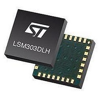
LSM303DLHTR STMicroelectronics, LSM303DLHTR Datasheet - Page 24

LSM303DLHTR
Manufacturer Part Number
LSM303DLHTR
Description
IC ACCELEROMETER 3AXIS 3D 28LGA
Manufacturer
STMicroelectronics
Datasheet
1.STEVAL-MKI063V1.pdf
(47 pages)
Specifications of LSM303DLHTR
Output Type
Digital - I²C
Sensor Type
Accelerometer and Magnetometer
Sensing Axis
Triple
Acceleration
2 g, 4 g, 8 g
Sensitivity
1 mg/digit, 2 mg/digit, 3.9 mg/digit
Package / Case
LGA-28L
Digital Output - Number Of Bits
16 bit
Supply Voltage (max)
3.3 V
Supply Voltage (min)
2.5 V
Maximum Operating Temperature
+ 85 C
Minimum Operating Temperature
- 30 C
Digital Output - Bus Interface
I2C
For Use With
497-10689 - BOARD ADAPTER LSM303DLH DIL24
Lead Free Status / RoHS Status
Lead free / RoHS Compliant
Other names
497-10765-2
LSM303DLHTR
LSM303DLHTR
Available stocks
Company
Part Number
Manufacturer
Quantity
Price
Company:
Part Number:
LSM303DLHTR
Manufacturer:
ST
Quantity:
8 295
Company:
Part Number:
LSM303DLHTR-SMJ
Manufacturer:
ST
Quantity:
8 305
Digital interfaces
7.1.1
24/47
I
The transaction on the bus is started through a START (ST) signal. A START condition is
defined as a HIGH to LOW transition on the data line while the SCL line is held HIGH. After
this has been transmitted by the master, the bus is considered busy. The next byte of data
transmitted after the start condition contains the address of the slave in the first 7 bits and
the 8th bit tells whether the master is receiving data from the slave or transmitting data to
the slave. When an address is sent, each device in the system compares the first seven bits
after a start condition with its address. If they match, the device considers itself addressed
by the master.
Data transfer with acknowledge is mandatory. The transmitter must release the SDA line
during the acknowledge pulse. The receiver must then pull the data line LOW so that it
remains stable low during the HIGH period of the acknowledge clock pulse. A receiver which
has been addressed is obliged to generate an acknowledge after each byte of data
received.
The I
protocol must be adhered to. After the start condition (ST) a slave address is sent. Once a
slave acknowledge (SAK) has been returned, an 8-bit sub-address (SUB) is transmitted: the
7 LSb represent the actual register address while the MSB enables address auto-increment.
If the MSb of the SUB field is ‘1’, the SUB (register address) is automatically increased to
allow multiple data read/write.
Table 11.
Table 12.
Table 13.
Data are transmitted in byte format (DATA). Each data transfer contains 8 bits. The number
of bytes transferred per transfer is unlimited. Data is transferred with the most significant bit
(MSb) first. If a receiver cannot receive another complete byte of data until it has performed
some other function, it can hold the clock line SCL LOW to force the transmitter into a wait
state. Data transfer only continues when the receiver is ready for another byte and releases
the data line. If a slave receiver does not acknowledge the slave address (i.e. it is not able to
receive because it is performing a real-time function) the data line must be left HIGH by the
slave. The master can then abort the transfer. A LOW to HIGH transition on the SDA line
while the SCL line is HIGH is defined as a STOP condition. Each data transfer must be
terminated by the generation of a STOP (SP) condition.
2
Master
Master
Slave
C operation
Slave
Master
Slave
2
C embedded inside the LSM303DLH behaves like a slave device and the following
ST
ST
Transfer when master is writing one byte to slave
Transfer when master is writing multiple bytes to slave
Transfer when master is receiving (reading) one byte of data from slave
ST
SAD + W
SAD + W
SAD + W
SAK
SAK
Doc ID 16941 Rev 1
SUB
SAK
SUB
SAK
SAK
SUB
SR
SAD + R
DATA
SAK
SAK
SAK
DATA
DATA
DATA
SAK
LSM303DLH
NMAK
SAK
SP
SP
SP


