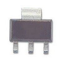
BDP949 Infineon Technologies, BDP949 Datasheet

BDP949
Specifications of BDP949
Available stocks
Related parts for BDP949
BDP949 Summary of contents
Page 1
... Application Note Thermal Resistance thJA Pin Configuration 1=B 2=C 3=E 4=C 1=B 2=C 3=E 4=C Symbol V CEO V CBO V EBO tot stg Symbol R thJS 1 BDP947, BDP949 Package - - SOT223 - - SOT223 Value Unit 200 mA 500 3 W 150 °C -65 ... 150 Value Unit ≤ 17 K/W 2006-01-24 3 ...
Page 2
... Electrical Characteristics at T Parameter DC Characteristics Collector-emitter breakdown voltage mA BDP947 mA BDP949 C B Collector-base breakdown voltage I = 100 µ BDP947 100 µ BDP949 C E Emitter-base breakdown voltage = 10 µ Collector-base cutoff current 150 ° Emitter-base cutoff current current gain mA 500 mA Collector-emitter saturation voltage 0 Base emitter saturation voltage ...
Page 3
... Collector-emitter saturation voltage C = ƒ Collector current -50°C 25°C 100° 0.8 1 1.3 V BEsat 3 BDP947, BDP949 ), CEsat 100°C 25°C 2 -50° 0.1 0.2 0.3 0.4 = ƒ 0.2 0.4 0.6 0.8 2006-01-24 V 0.6 V CEsat -50°C 25°C 100° 1.3 ...
Page 4
... Collector-base capacitance C A Emitter-base capacitance C 500 pF 400 350 300 250 200 150 typ 100 50 100 120 °C 150 ƒ Permissible Pulse Load R tot 120 °C 100 150 BDP947, BDP949 cb = ƒ CEB ƒ thJS 0.5 0.2 0 0.1 0.05 0.02 0.01 0.005 2006-01-24 = ƒ ...
Page 5
... Permissible Pulse Load = ƒ totmax totDC 0.005 0.01 0.02 0.05 0.1 0.2 0 BDP947, BDP949 2006-01-24 ...
Page 6
... Reel ø180 mm = 1.000 Pieces/Reel Reel ø330 mm = 4.000 Pieces/Reel Pin 1 Package SOT223 6.5 ±0 ±0 2.3 0.7 ±0.1 4.6 0. 3.5 1.2 1.1 Manufacturer Date code (Year/Calendarweek) Type code Example 8 6.8 6 BDP947, BDP949 1.6 ±0.1 0.1 MAX 2005, June BCP52-16 0.3 MAX. 1.75 2006-01-24 ...
Page 7
... Life support devices or systems are intended to be implanted in the human body support and/or maintain and sustain and/or protect human life. If they fail reasonable to assume that the health of the user or other persons may be endangered. BDP947, BDP949 7 2006-01-24 ...


