AC164139 Microchip Technology, AC164139 Datasheet - Page 199
AC164139
Manufacturer Part Number
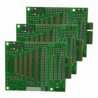
AC164139
Description
Graphics Display Prototype Board Graphics
Manufacturer
Microchip Technology
Specifications of AC164139
Main Purpose
LCD Development
Embedded
No
Utilized Ic / Part
PICtail™ Plus Board
Lead Free Status / RoHS Status
Lead free / RoHS Compliant
Secondary Attributes
-
Primary Attributes
-
Lead Free Status / RoHS Status
Lead free / RoHS Compliant
Available stocks
Company
Part Number
Manufacturer
Quantity
Price
Company:

Part Number:
AC164139
Manufacturer:
Microchip Technology
Quantity:
135


REGISTER 13-1:
2010 Microchip Technology Inc.
bit 15
bit 7
Legend:
R = Readable bit
-n = Value at POR
bit 15-14
bit 13
bit 12-10
bit 9-7
bit 6-5
bit 4
bit 3
bit 2-0
Note 1:
U-0
U-0
—
—
The ICx input must also be configured to an available RPn/RPIn pin. For more information, see
Section 10.4 “Peripheral Pin Select (PPS)”.
Unimplemented: Read as ‘0’
ICSIDL: Input Capture x Module Stop in Idle Control bit
1 = Input capture module halts in CPU Idle mode
0 = Input capture module continues to operate in CPU Idle mode
ICTSEL<2:0>: Input Capture Timer Select bits
111 = System clock (F
110 = Reserved
101 = Reserved
100 = Timer1
011 = Timer5
010 = Timer4
001 = Timer2
000 = Timer3
Unimplemented: Read as ‘0’
ICI<1:0>: Select Number of Captures Per Interrupt bits
11 = Interrupt on every fourth capture event
10 = Interrupt on every third capture event
01 = Interrupt on every second capture event
00 = Interrupt on every capture event
ICOV: Input Capture x Overflow Status Flag bit (read-only)
1 = Input capture overflow occurred
0 = No input capture overflow occurred
ICBNE: Input Capture x Buffer Empty Status bit (read-only)
1 = Input capture buffer is not empty, at least one more capture value can be read
0 = Input capture buffer is empty
ICM<2:0>: Input Capture Mode Select bits
111 = Interrupt mode: input capture functions as an interrupt pin only when the device is in Sleep or
110 = Unused (module disabled)
101 = Prescaler Capture mode: capture on every 16
100 = Prescaler Capture mode: capture on every 4
011 = Simple Capture mode: capture on every rising edge
010 = Simple Capture mode: capture on every falling edge
001 = Edge Detect Capture mode: capture on every edge (rising and falling), ICI<1:0> bits do not
000 = Input capture module turned off
R/W-0
ICI1
U-0
—
ICxCON1: INPUT CAPTURE x CONTROL REGISTER 1
Idle mode (rising edge detect only, all other control bits are not applicable)
control interrupt generation for this mode
HSC = Hardware Settable/Clearable bit
W = Writable bit
‘1’ = Bit is set
ICSIDL
R/W-0
R/W-0
ICI0
OSC
/2)
R-0, HSC
ICTSEL2
PIC24FJ256DA210 FAMILY
R/W-0
ICOV
(1)
U = Unimplemented bit, read as ‘0’
‘0’ = Bit is cleared
R-0, HSC
ICTSEL1
ICBNE
R/W-0
th
th
rising edge
rising edge
ICTSEL0
ICM2
R/W-0
R/W-0
(1)
x = Bit is unknown
ICM1
R/W-0
U-0
—
(1)
DS39969B-page 199
ICM0
R/W-0
U-0
—
(1)
bit 8
bit 0
Related parts for AC164139
Image
Part Number
Description
Manufacturer
Datasheet
Request
R

Part Number:
Description:
Manufacturer:
Microchip Technology Inc.
Datasheet:
Part Number:
Description:
Manufacturer:
Microchip Technology Inc.
Datasheet:
Part Number:
Description:
Manufacturer:
Microchip Technology Inc.
Datasheet:
Part Number:
Description:
Manufacturer:
Microchip Technology Inc.
Datasheet:
Part Number:
Description:
Manufacturer:
Microchip Technology Inc.
Datasheet:
Part Number:
Description:
Manufacturer:
Microchip Technology Inc.
Datasheet:
Part Number:
Description:
Manufacturer:
Microchip Technology Inc.
Datasheet:
Part Number:
Description:
Manufacturer:
Microchip Technology Inc.
Datasheet: