AC164139 Microchip Technology, AC164139 Datasheet - Page 249
AC164139
Manufacturer Part Number
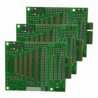
AC164139
Description
Graphics Display Prototype Board Graphics
Manufacturer
Microchip Technology
Specifications of AC164139
Main Purpose
LCD Development
Embedded
No
Utilized Ic / Part
PICtail™ Plus Board
Lead Free Status / RoHS Status
Lead free / RoHS Compliant
Secondary Attributes
-
Primary Attributes
-
Lead Free Status / RoHS Status
Lead free / RoHS Compliant
Available stocks
Company
Part Number
Manufacturer
Quantity
Price
Company:

Part Number:
AC164139
Manufacturer:
Microchip Technology
Quantity:
135


18.3.1
Unlike device level interrupts, the USB OTG interrupt
status flags are not freely writable in software. All USB
OTG flag bits are implemented as hardware set only
bits. Additionally, these bits can only be cleared in
FIGURE 18-10:
18.4
The following section describes how to perform a com-
mon Device mode task. In Device mode, USB transfers
are performed at the transfer level. The USB module
automatically performs the status phase of the transfer.
18.4.1
1.
2.
3.
4.
2010 Microchip Technology Inc.
Differential Data
Note 1:
Reset the Ping-Pong Buffer Pointers by setting,
then clearing, the Ping-Pong Buffer Reset bit,
PPBRST (U1CON<1>).
Disable all interrupts (U1IE and U1EIE = 00h).
Clear any existing interrupt flags by writing FFh
to U1IR and U1EIR.
Verify that V
only).
Device Mode Operation
CLEARING USB OTG INTERRUPTS
ENABLING DEVICE MODE
USB Reset
The control transfer shown here is only an example showing events that can occur for every transaction. Typical
control transfers will spread across multiple frames.
URSTIF
RESET
BUS
Start-Of-Frame (SOF)
is present (non OTG devices
EXAMPLE OF A USB TRANSACTION AND INTERRUPT EVENTS
SOFIF
SOF
SETUP
PIC24FJ256DA210 FAMILY
DATA
STATUS
software by writing a ‘1’ to their locations (i.e., perform-
ing a MOV type instruction). Writing a ‘0’ to a flag bit (i.e.,
a BCLR instruction) has no effect.
5.
6.
7.
8.
9.
OUT Token Empty Data
SETUP Token
From Host
From Host
From Host From Host
Control Transfer
IN Token
Note:
Enable the USB module by setting the USBEN
bit (U1CON<0>).
Set the OTGEN bit (U1OTGCON<2>) to enable
OTG operation.
Enable the endpoint zero buffer to receive the
first setup packet by setting the EPRXEN and
EPHSHK bits for Endpoint 0 (U1EP0<3,0> = 1).
Power up the USB module by setting the
USBPWR bit (U1PWRC<0>).
Enable the D+ pull-up resistor to signal an attach
by setting DPPULUP bit (U1OTGCON<7>).
Transaction
Throughout this data sheet, a bit that can
only be cleared by writing a ‘1’ to its loca-
tion is referred to as “Write 1 to clear”. In
register descriptions, this function is
indicated by the descriptor, “K”.
To Host
From Host
Data
Data
(1)
From Host
To Host
To Host
ACK
ACK
ACK
SOF
1 ms Frame
DS39969B-page 249
Transaction
Set TRNIF
Set TRNIF
Set TRNIF
Complete
Related parts for AC164139
Image
Part Number
Description
Manufacturer
Datasheet
Request
R

Part Number:
Description:
Manufacturer:
Microchip Technology Inc.
Datasheet:
Part Number:
Description:
Manufacturer:
Microchip Technology Inc.
Datasheet:
Part Number:
Description:
Manufacturer:
Microchip Technology Inc.
Datasheet:
Part Number:
Description:
Manufacturer:
Microchip Technology Inc.
Datasheet:
Part Number:
Description:
Manufacturer:
Microchip Technology Inc.
Datasheet:
Part Number:
Description:
Manufacturer:
Microchip Technology Inc.
Datasheet:
Part Number:
Description:
Manufacturer:
Microchip Technology Inc.
Datasheet:
Part Number:
Description:
Manufacturer:
Microchip Technology Inc.
Datasheet: