AC164139 Microchip Technology, AC164139 Datasheet - Page 206
AC164139
Manufacturer Part Number
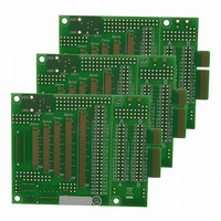
AC164139
Description
Graphics Display Prototype Board Graphics
Manufacturer
Microchip Technology
Specifications of AC164139
Main Purpose
LCD Development
Embedded
No
Utilized Ic / Part
PICtail™ Plus Board
Lead Free Status / RoHS Status
Lead free / RoHS Compliant
Secondary Attributes
-
Primary Attributes
-
Lead Free Status / RoHS Status
Lead free / RoHS Compliant
Available stocks
Company
Part Number
Manufacturer
Quantity
Price
Company:

Part Number:
AC164139
Manufacturer:
Microchip Technology
Quantity:
135


PIC24FJ256DA210 FAMILY
REGISTER 14-1:
DS39969B-page 206
bit 15
bit 7
Legend:
R = Readable bit
-n = Value at POR
bit 15-14
bit 13
bit 12-10
bit 9
bit 8
bit 7
bit 6
bit 5
bit 4
Note 1:
ENFLT0
R/W-0
U-0
—
2:
3:
4:
(2)
The OCx output must also be configured to an available RPn pin. For more information, see Section 10.4
“Peripheral Pin Select (PPS)”.
The Fault input enable and Fault status bits are valid when OCM<2:0> = 111 or 110.
The Comparator 1 output controls the OC1-OC3 channels; Comparator 2 output controls the OC4-OC6
channels; Comparator 3 output controls the OC7-OC9 channels.
The OCFA/OCFB Fault input must also be configured to an available RPn/RPIn pin. For more information,
see Section 10.4 “Peripheral Pin Select (PPS)”.
Unimplemented: Read as ‘0’
OCSIDL: Stop Output Compare x in Idle Mode Control bit
1 = Output Compare x halts in CPU Idle mode
0 = Output Compare x continues to operate in CPU Idle mode
OCTSEL<2:0>: Output Compare x Timer Select bits
111 = Peripheral clock (F
110 = Reserved
101 = Reserved
100 = Timer1 clock (only synchronous clock is supported)
011 = Timer5 clock
010 = Timer4 clock
001 = Timer3 clock
000 = Timer2 clock
ENFLT2: Fault Input 2 Enable bit
1 = Fault 2 (Comparator 1/2/3 out) is enabled
0 = Fault 2 is disabled
ENFLT1: Fault Input 1 Enable bit
1 = Fault 1 (OCFB pin) is enabled
0 = Fault 1 is disabled
ENFLT0: Fault Input 0 Enable bit
1 = Fault 0 (OCFA pin) is enabled
0 = Fault 0 is disabled
OCFLT2: PWM Fault 2 (Comparator 1/2/3) Condition Status bit
1 = PWM Fault 2 has occurred
0 = No PWM Fault 2 has occurred
OCFLT1: PWM Fault 1 (OCFB pin) Condition Status bit
1 = PWM Fault 1 has occurred
0 = No PWM Fault 1 has occurred
OCFLT0: PWM Fault 0 (OCFA pin) Condition Status bit
1 = PWM Fault 0 has occurred
0 = No PWM Fault 0 has occurred
R/W-0, HSC R/W-0, HSC R/W-0, HSC
OCFLT2
U-0
—
OCxCON1: OUTPUT COMPARE x CONTROL REGISTER 1
(2)
HSC = Hardware Settable/Clearable bit
W = Writable bit
‘1’ = Bit is set
OCFLT1
OCSIDL
R/W-0
(2)
CY
)
OCFLT0
OCTSEL2
R/W-0
(2)
(2)
(2)
(4)
(4)
(2)
U = Unimplemented bit, read as ‘0’
‘0’ = Bit is cleared
TRIGMODE
OCTSEL1
(3)
R/W-0
R/W-0
(2,4)
(2,4)
OCTSEL0
OCM2
R/W-0
R/W-0
(2,3)
(1)
2010 Microchip Technology Inc.
x = Bit is unknown
ENFLT2
OCM1
R/W-0
R/W-0
(1)
(2)
ENFLT1
OCM0
R/W-0
R/W-0
(1)
bit 8
bit 0
(2)
Related parts for AC164139
Image
Part Number
Description
Manufacturer
Datasheet
Request
R

Part Number:
Description:
Manufacturer:
Microchip Technology Inc.
Datasheet:
Part Number:
Description:
Manufacturer:
Microchip Technology Inc.
Datasheet:
Part Number:
Description:
Manufacturer:
Microchip Technology Inc.
Datasheet:
Part Number:
Description:
Manufacturer:
Microchip Technology Inc.
Datasheet:
Part Number:
Description:
Manufacturer:
Microchip Technology Inc.
Datasheet:
Part Number:
Description:
Manufacturer:
Microchip Technology Inc.
Datasheet:
Part Number:
Description:
Manufacturer:
Microchip Technology Inc.
Datasheet:
Part Number:
Description:
Manufacturer:
Microchip Technology Inc.
Datasheet: