AC164139 Microchip Technology, AC164139 Datasheet - Page 97
AC164139
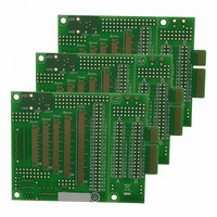
Manufacturer Part Number
AC164139
Description
Graphics Display Prototype Board Graphics
Manufacturer
Microchip Technology
Specifications of AC164139
Main Purpose
LCD Development
Embedded
No
Utilized Ic / Part
PICtail™ Plus Board
Lead Free Status / RoHS Status
Lead free / RoHS Compliant
Secondary Attributes
-
Primary Attributes
-
Lead Free Status / RoHS Status
Lead free / RoHS Compliant
Available stocks
Company
Part Number
Manufacturer
Quantity
Price
Company:

Part Number:
AC164139
Manufacturer:
Microchip Technology
Quantity:
135


The CORCON register contains the IPL3 bit, which,
together with IPL<2:0>, indicates the current CPU
priority level. IPL3 is a read-only bit so that trap events
cannot be masked by the user software.
The interrupt controller has the Interrupt Controller Test
register, INTTREG, which displays the status of the
interrupt controller. When an interrupt request occurs,
it’s associated vector number and the new interrupt pri-
ority level are latched into INTTREG. This information
can be used to determine a specific interrupt source if
REGISTER 7-1:
2010 Microchip Technology Inc.
bit 15
bit 7
Legend:
R = Readable bit
-n = Value at POR
bit 15-9
bit 7-5
Note 1:
R/W-0, HSC
IPL2
U-0
—
2:
3:
(2,3)
See Register 3-1 for the description of the remaining bits (bit 8, 4, 3, 2, 1 and 0) that are not dedicated to
interrupt control functions.
The IPL bits are concatenated with the IPL3 (CORCON<3>) bit to form the CPU interrupt priority level.
The value in parentheses indicates the interrupt priority level if IPL3 = 1.
The IPL Status bits are read-only when NSTDIS (INTCON1<15>) = 1.
Unimplemented: Read as ‘0’
IPL<2:0>: CPU Interrupt Priority Level Status bits
111 = CPU interrupt priority level is 7 (15); user interrupts are disabled
110 = CPU interrupt priority level is 6 (14)
101 = CPU interrupt priority level is 5 (13)
100 = CPU interrupt priority level is 4 (12)
011 = CPU interrupt priority level is 3 (11)
010 = CPU interrupt priority level is 2 (10)
001 = CPU interrupt priority level is 1 (9)
000 = CPU interrupt priority level is 0 (8)
R/W-0, HSC R/W-0, HSC
IPL1
U-0
—
SR: ALU STATUS REGISTER (IN CPU)
(2,3)
HSC = Hardware Settable/Clearable bit
W = Writable bit
‘1’ = Bit is set
IPL0
U-0
—
(2,3)
R-0, HSC
PIC24FJ256DA210 FAMILY
RA
U-0
—
(1)
U = Unimplemented bit, read as ‘0’
R/W-0, HSC
‘0’ = Bit is cleared
a generic ISR is used for multiple vectors (such as
when ISR remapping is used in bootloader applica-
tions) or to check if another interrupt is pending while in
an ISR.
All interrupt registers are described in Register 7-1
through Register 7-40 in the succeeding pages.
U-0
N
—
(1)
(2,3)
R/W-0, HSC
OV
U-0
—
(1)
x = Bit is unknown
R/W-0, HSC R/W-0, HSC
U-0
Z
—
(1)
DS39969B-page 97
R-0, HSC
DC
C
(1)
(1)
bit 8
bit 0
Related parts for AC164139
Image
Part Number
Description
Manufacturer
Datasheet
Request
R

Part Number:
Description:
Manufacturer:
Microchip Technology Inc.
Datasheet:
Part Number:
Description:
Manufacturer:
Microchip Technology Inc.
Datasheet:
Part Number:
Description:
Manufacturer:
Microchip Technology Inc.
Datasheet:
Part Number:
Description:
Manufacturer:
Microchip Technology Inc.
Datasheet:
Part Number:
Description:
Manufacturer:
Microchip Technology Inc.
Datasheet:
Part Number:
Description:
Manufacturer:
Microchip Technology Inc.
Datasheet:
Part Number:
Description:
Manufacturer:
Microchip Technology Inc.
Datasheet:
Part Number:
Description:
Manufacturer:
Microchip Technology Inc.
Datasheet: