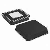
ADUC7061BCPZ32 Analog Devices Inc, ADUC7061BCPZ32 Datasheet - Page 12

ADUC7061BCPZ32
Manufacturer Part Number
ADUC7061BCPZ32
Description
DUAL 24-BIT AFE AND ARM 7 I.C
Manufacturer
Analog Devices Inc
Series
MicroConverter® ADuC7xxxr
Datasheet
1.EVAL-ADUC7061MKZ.pdf
(108 pages)
Specifications of ADUC7061BCPZ32
Design Resources
USB Based Temperature Monitor Using ADuC7061 and an External RTD (CN0075) 4 mA-to-20 mA Loop-Powered Temperature Monitor Using ADuC7060/1 (CN0145)
Core Processor
ARM7
Core Size
16/32-Bit
Speed
10MHz
Connectivity
I²C, SPI, UART/USART
Peripherals
POR, PWM, Temp Sensor, WDT
Number Of I /o
8
Program Memory Size
32KB (32K x 8)
Program Memory Type
FLASH
Ram Size
4K x 8
Voltage - Supply (vcc/vdd)
2.375 V ~ 2.625 V
Data Converters
A/D 5x24b, 8x24b, D/A 1x14b
Oscillator Type
Internal
Operating Temperature
-40°C ~ 125°C
Package / Case
32-LFCSP
Package
32LFCSP EP
Device Core
ARM7TDMI
Family Name
ADuC7xxx
Maximum Speed
10.24 MHz
Operating Supply Voltage
2.5 V
Data Bus Width
16|32 Bit
Number Of Programmable I/os
14
Interface Type
I2C/SPI/UART
On-chip Adc
2(4-chx24-bit)
Number Of Timers
4
Lead Free Status / RoHS Status
Lead free / RoHS Compliant
Eeprom Size
-
Lead Free Status / RoHS Status
Lead free / RoHS Compliant
Available stocks
Company
Part Number
Manufacturer
Quantity
Price
Company:
Part Number:
ADUC7061BCPZ32
Manufacturer:
AD
Quantity:
3 100
Company:
Part Number:
ADUC7061BCPZ32
Manufacturer:
ADI
Quantity:
538
Part Number:
ADUC7061BCPZ32
Manufacturer:
ADI/亚德诺
Quantity:
20 000
ADuC7060/ADuC7061
Table 5. SPI Slave Mode Timing (Phase Mode = 1)
Parameter
t
t
t
t
t
t
t
t
t
t
t
1
CS
SL
SH
DAV
DSU
DHD
DF
DR
SR
SF
SFS
t
UCLK
= 97.6 ns. It corresponds to the 10.24 MHz internal clock from the PLL.
(POLARITY = 0)
(POLARITY = 1)
(POLARITY = 0)
(POLARITY = 1)
Description
CS to SCLOCK edge
SCLOCK low pulse width
SCLOCK high pulse width
Data output valid after SCLOCK edge
Data input setup time before SCLOCK edge
Data input hold time after SCLOCK edge
Data output fall time
Data output rise time
SCLOCK rise time
SCLOCK fall time
CS high after SCLOCK edge
SCLOCK
SCLOCK
SCLOCK
SCLOCK
MOSI
MISO
MISO
MOSI
CS
1
t
t
CS
DOSU
t
DSU
MSB IN
t
t
DSU
DAV
MSB
t
DHD
t
t
SH
SH
Figure 4. SPI Master Mode Timing (Phase Mode = 0)
Figure 5. SPI Slave Mode Timing (Phase Mode = 1)
t
DF
MSB IN
t
DAV
1
t
DHD
t
t
MSB
1
SL
SL
Rev. B | Page 12 of 108
t
DR
t
BITS 6 TO 1
DF
BITS 6 TO 1
Min
(2 × t
1 × t
2 × t
1
1
0
t
UCLK
UCLK
DR
BITS 6 TO 1
HCLK
BITS 6 TO 1
) + (2 × t
UCLK
t
LSB IN
t
SR
SR
)
LSB
Typ
(SPIDIV + 1) × t
(SPIDIV + 1) × t
30
30
LSB IN
t
t
SF
SF
LSB
t
SFS
HCLK
HCLK
Max
40
40
40
Unit
ns
ns
ns
ns
ns
ns
ns
ns
ns
ns
ns


