RUR1S1560S9A Fairchild Semiconductor, RUR1S1560S9A Datasheet
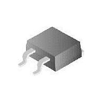
DIODE ULTRA FAST 15A 600V D2PAK

RUR1S1560S9A

Manufacturer Part Number
RUR1S1560S9A
Description
DIODE ULTRA FAST 15A 600V D2PAK
Manufacturer
Fairchild Semiconductor
Datasheet

Specifications of RUR1S1560S9A

Voltage - Forward (vf) (max) @ If
1.5V @ 15A
Voltage - Dc Reverse (vr) (max)
600V
Current - Average Rectified (io)
15A
Current - Reverse Leakage @ Vr
100µA @ 600V
Diode Type
Standard
Speed
Fast Recovery =< 500ns, > 200mA (Io)
Reverse Recovery Time (trr)
60ns
Mounting Type
Surface Mount
Package / Case
D²Pak, TO-263 (2 leads + tab)
Product
Ultra Fast Recovery Rectifier
Configuration
Single
Reverse Voltage
600 V
Forward Voltage Drop
1.5 V
Recovery Time
60 ns
Forward Continuous Current
15 A
Max Surge Current
200 A
Reverse Current Ir
100 uA
Power Dissipation
100 W
Mounting Style
SMD/SMT
Maximum Operating Temperature
+ 175 C
Minimum Operating Temperature
- 55 C
Lead Free Status / RoHS Status
Lead free / RoHS Compliant
Capacitance @ Vr, F
-
Lead Free Status / Rohs Status
Lead free / RoHS Compliant

Available stocks

Company
Part Number
Manufacturer
Quantity
Price
Part Number:
RUR1S1560S9A
Manufacturer:
FAIRCHILD
Quantity:
26 572
©2002 Fairchild Semiconductor Corporation
15A, 600V Ultrafast Diode
The RUR1S1560S is an ultrafast diode (t
recovery characteristics. It has low forward voltage drop and
is of silicon nitride passivated ion-implanted, epitaxial planar
construction.
This device is intended for use as freewheeling/clamping
diode and rectifier in a variety of switching power supplies
and other power switching applications. Its low stored charge
and ultrafast soft recovery minimizes ringing and electrical
noise in many power switching circuits, thus reducing power
loss in the switching transistor.
Formerly developmental type TA9905.
Ordering Information
NOTE: When ordering, use the entire part number. Add the suffix 9A
to obtain the TO-263 variant in tape and reel, i.e. RUR1S1560S9A.
Symbol
Absolute Maximum Ratings
NOTES:
CAUTION: Stresses above those listed in “Absolute Maximum Ratings” may cause permanent damage to the device. This is a stress only rating and operation of the
device at these or any other conditions above those indicated in the operational sections of this specification is not implied.
RUR1S1560S
THERMAL SPECIFICATIONS
PART NUMBER
SYMBOL
T
V
J
V
I
E
R
I
I
R
F(AV)
T
, T
RWM
FRM
FSM
RRM
V
P
T
AVL
pkg
R
D
L
JC
JA
STG
TO-263
Peak Repetitive Reverse Voltage
Working Peak Reverse Voltage
DC Blocking Voltage
Average Rectified Forward Current
Repetitive Peak Surge Current (20kHz Square Wave)
Nonrepetitive Peak Surge Current (Halfwave 1 Phase 60Hz)
Power Dissipation
Avalanche Energy (1A, 40mH)
Operating and Storage Temperature
Maximum Temperature for Soldering
Thermal Resistance Junction to Case
Thermal Resistance Junction to Ambient
PACKAGE
Leads at 0.063in (1.6mm) from Case for 10s
Package Body for 10s, See Techbrief TB334
Data Sheet
K
A
T
C
= 25
RUR1560
rr
o
< 55ns) with soft
C, Unless Otherwise Specified
BRAND
PARAMETER
Features
• Ultrafast Recovery . . . . . . . . . . . . . . . . . . . . . . . . t
• Operating Temperature . . . . . . . . . . . . . . . . . . . . . . 175
• Reverse Voltage . . . . . . . . . . . . . . . . . . . . . . . . . . . . 600V
• Avalanche Energy Rated
Applications
• Switching Power Supplies
• Power Switching Circuits
• General Purpose
Packaging
CATHODE
ANODE
JEDEC TO-263
RUR1S1560S
-55 to 175
600
600
600
200
100
300
260
1.5
15
30
20
60
RUR1S1560S
September 2002
CATHODE
(FLANGE)
RUR1S1560S Rev. A1
UNITS
o
o
C/W
C/W
mJ
o
o
o
W
rr
V
V
V
A
A
A
C
C
C
< 55ns
o
C

Related parts for RUR1S1560S9A

RUR1S1560S9A Summary of contents

Page 1

... Formerly developmental type TA9905. Ordering Information PART NUMBER PACKAGE RUR1S1560S TO-263 NOTE: When ordering, use the entire part number. Add the suffix 9A to obtain the TO-263 variant in tape and reel, i.e. RUR1S1560S9A. Symbol K A Absolute Maximum Ratings T C SYMBOL ...

Page 2

... Instantaneous reverse current Reverse recovery time (See Figure 9), summation Time to reach peak reverse current (See Figure 9 Time from peak I to projected zero crossing pulse width duty cycle. ©2002 Fairchild Semiconductor Corporation o C, Unless Otherwise Specified TEST CONDITION 30V R = 30V R = 30V R = 30V ...

Page 3

... AMPLITUDE AND GE R CONTROL dI / CONTROL I 1 AND MOS IRF840 FIGURE 5. t TEST CIRCUIT rr ©2002 Fairchild Semiconductor Corporation 100 0.010 0.001 1.2 1.4 1.6 1.8 FIGURE 2. REVERSE VOLTAGE vs REVERSE CURRENT 100 CURVES vs FIGURE 4. 6. TYPICAL CURRENT DERATING CURVE vs B DUT CURRENT SENSE + ...

Page 4

... Test Circuits and Waveforms 40mH R < 0 50V 1/2LI [V /( AVL R(AVL) R(AVL IGBT (BV > DUT CES R(AVL) CURRENT SENSE Q 1 DUT FIGURE 7. AVALANCHE ENERGY TEST CIRCUIT ©2002 Fairchild Semiconductor Corporation (Continued FIGURE 8. AVALANCHE CURRENT AND VOLTAGE V AVL WAVEFORMS RUR1S1560S Rev ...

Page 5

CROSSVOLT â â â â ...

Related keywords