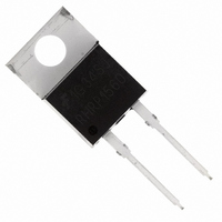
RHRP1560 Fairchild Semiconductor, RHRP1560 Datasheet - Page 2

RHRP1560
Manufacturer Part Number
RHRP1560
Description
DIODE HYPER 600V 15A TO-220AC
Manufacturer
Fairchild Semiconductor
Datasheet
1.RHRP1560.pdf
(5 pages)
Specifications of RHRP1560
Voltage - Forward (vf) (max) @ If
2.1V @ 15A
Voltage - Dc Reverse (vr) (max)
600V
Current - Average Rectified (io)
15A
Current - Reverse Leakage @ Vr
100µA @ 600V
Diode Type
Standard
Speed
Fast Recovery =< 500ns, > 200mA (Io)
Reverse Recovery Time (trr)
40ns
Mounting Type
Through Hole
Package / Case
TO-220-2, TO-220AC
Product
Ultra Fast Recovery Rectifier
Configuration
Single
Reverse Voltage
600 V
Forward Voltage Drop
2.1 V
Recovery Time
40 ns
Forward Continuous Current
15 A
Max Surge Current
200 A
Reverse Current Ir
100 uA
Power Dissipation
100 W
Mounting Style
Through Hole
Maximum Operating Temperature
+ 175 C
Minimum Operating Temperature
- 65 C
Repetitive Reverse Voltage Vrrm Max
600V
Forward Current If(av)
15A
Forward Voltage Vf Max
2.1V
Reverse Recovery Time Trr Max
40ns
Forward Surge Current Ifsm Max
200A
Rohs Compliant
Yes
Lead Free Status / RoHS Status
Lead free / RoHS Compliant
Capacitance @ Vr, F
-
Lead Free Status / Rohs Status
Lead free / RoHS Compliant
Available stocks
Company
Part Number
Manufacturer
Quantity
Price
Company:
Part Number:
RHRP1560
Manufacturer:
FSC
Quantity:
9 182
Company:
Part Number:
RHRP1560
Manufacturer:
FSC
Quantity:
1 950
Company:
Part Number:
RHRP1560
Manufacturer:
FAIRCHILD
Quantity:
15
Part Number:
RHRP1560
Manufacturer:
FAIRCHILD/仙童
Quantity:
20 000
©2002 Fairchild Semiconductor Corporation
Electrical Specifications
DEFINITIONS
Typical Performance Curves
R
Q
θ JC
FIGURE 1. FORWARD CURRENT vs FORWARD VOLTAGE
RR
pw = Pulse Width.
V
C
I
t
t
t
D = Duty Cycle.
R
F
rr
a
b
SYMBOL
J
100
0.5
10
= Instantaneous forward voltage (pw = 300 µ s, D = 2%).
= Instantaneous reverse current .
= Reverse recovery time (See Figure 9), summation of t
= Time to reach peak reverse current (See Figure 9).
= Time from peak I
= Reverse Recovery Change.
= Junction Capacitance.
= Thermal resistance junction to case.
R
Q
1
V
C
I
t
t
t
θ JC
0
RR
R
rr
a
b
F
J
175
o
0.5
C
I
I
V
V
V
V
I
I
I
I
I
V
100
F
F
F
F
F
F
F
R
R
R
R
R
= 15A
= 15A, T
= 1A, dI
= 15A, dI
= 15A, dI
= 15A, dI
= 15A, dI
o
= 400V
= 600V
= 400V, T
= 600V, T
= 10V, I
V
V
RM
C
F
F
, FORWARD VOLTAGE (V)
, FORWARD VOLTAGE (V)
1
to projected zero crossing of I
25
TEST CONDITION
F
o
C
F
/dt = 100A/ µ s
F
F
F
F
C
/dt = 100A/ µ s
/dt = 100A/ µ s
/dt = 100A/ µ s
/dt = 100A/ µ s
= 150
= 0A
C
C
T
1.5
= 150
= 150
C
= 25
o
C
o
o
C
C
o
C, Unless Otherwise Specified
2
2.5
RM
a
based on a straight line from peak I
MIN
+ t
-
-
-
-
-
-
-
-
-
-
-
-
-
3
b
.
RHRP1540
TYP
20
15
40
60
-
-
-
-
-
-
-
-
-
1000
0.01
100
FIGURE 2. REVERSE CURRENT vs REVERSE VOLTAGE
0.1
10
1
0
MAX
100
500
2.1
1.7
1.5
35
40
-
-
-
-
-
-
100
RM
MIN
-
-
-
-
-
-
-
-
-
-
-
-
-
through 25% of I
V
200
R
, REVERSE VOLTAGE (V)
RHRP1560
175
100
25
TYP
20
15
40
60
300
-
-
-
-
-
-
-
-
-
o
o
o
C
C
C
RM
RHRP1540, RHRP1560 Rev. B
(See Figure 9).
400
MAX
100
500
2.1
1.7
1.5
35
40
-
-
-
-
-
-
500
UNITS
o
C/W
µ A
µ A
µ A
µ A
nC
pF
ns
ns
ns
ns
V
V
600


