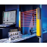
F39-EU1E Omron, F39-EU1E Datasheet - Page 193

F39-EU1E
Manufacturer Part Number
F39-EU1E
Description
F3S-B OPTIONAL PROGRAMMING KIT
Manufacturer
Omron
Datasheet
1.F39-EU1E.pdf
(865 pages)
Specifications of F39-EU1E
Leaded Process Compatible
No
Peak Reflow Compatible (260 C)
No
Light Curtain Type
Safety
Lead Free Status / RoHS Status
Contains lead / RoHS non-compliant
Lead Free Status / RoHS Status
Contains lead / RoHS non-compliant
- Current page: 193 of 865
- Download datasheet (35Mb)
Courtesy of Steven Engineering, Inc.-230 Ryan Way, South San Francisco, CA 94080-6370-Main Office: (650) 588-9200-Outside Local Area: (800) 258-9200-www.stevenengineering.com
Operation
Functions
Auto Switching Function
The following table shows the relationship between the safety inputs
and safety outputs of the G9SX-GS@ when auto switching is
selected.
Note: 1. If the logical AND connection input is enabled, it must be ON
Manual Switching Function
As shown in the following table, the relationship between the safety
inputs and safety outputs of the G9SX-GS@ depends on the setting
of the connected mode selector when manual switching is selected.
Mode Selector = Normal Operating Mode
(M1 = ON, M2 = OFF)
Mode Selector = Maintenance Mode (M1 = OFF, M2 = ON)
Note: 1. If the logical AND connection input is enabled, it must be ON
Logical AND Connection
The logical AND connection means that one Unit (Unit A) outputs a
safety signal “a” to a subsequent Unit (Unit B) and Unit B calculates
the logical AND between safety signal “a” and safety signal “b.” In the
example shown below, the logical AND connection results in a safety
output of “a AND b” for Unit B.
Note: For details on the logical AND connection, refer to the G9SX-
Safety input A
Safety input B
Safety output
Safety input A
Safety input B
Safety output
Safety input A
Safety input B
Safety output
2. Select either auto reset or manual reset for the reset mode,
2. Select either auto reset or manual reset for the reset mode,
series Flexible Safety Unit catalog (Cat. No. J150).
Unit A
as a necessary condition for the above table.
depending on the operation of the application.
as a necessary condition for the above table.
depending on the operation of the application.
a
a
http://www.ia.omron.com/
ON
ON
ON
ON
ON
ON
ON
ON
ON
ON
OFF
ON
ON
OFF
OFF
ON
OFF
ON
OFF
ON
ON
OFF
ON
ON
OFF
ON
OFF
a (AND) b
b
Unit B
OFF
OFF
OFF
OFF
OFF
OFF
OFF
OFF
OFF
External Indicator Outputs
The operator can be notified of two safety input states (enabled/
disabled) by connecting external indicator outputs UA and UB to
indicators. External indicator outputs UA and UB turn ON when safety
inputs A and B, respectively, are disabled, and turn OFF when safety
inputs A and B, respectively, are enabled.
If error monitor output X2 turns ON, UA and UB will both turn OFF.
Auto Switching Selected
Manual Switching Selected
Note: Fault of external indicators can be detected. (Refer to page 13.)
Auxiliary Outputs
Auxiliary outputs X1 to X4 can be used to notify the operator of input,
output, and error states, as shown in the following table.
Connecting Expansion Units
UA
UB
UA
UB
X1
X2
X3
X4
indicator output
indicator output
G9SX-GS226-T15-@
The G9SX-EX and G9SX-EX-T Expansion Units can be connected
to the G9SX-GS226-T15-@ to increase the number of safety
outputs.
A maximum of five Expansion Units can be connected to one
G9SX-GS226-T15-@. This may be a combination of the G9SX-EX
Instantaneous Expansion Unit and the G9SX-EX-T OFF-delayed
Expansion Unit.
Remove the terminating connector from the receptacle on the
G9SX-GS226-T15-@ and insert the Expansion Unit cable
connector into the receptacle. Insert the terminating connector into
the receptacle on the Expansion Unit at the very end (rightmost).
When Expansion Units are connected to the G9SX-GS226-T15-@,
make sure that power is supplied to every Expansion Unit. (Refer
to the following diagram for actual Expansion Unit connections.)
Terminal
External
External
name
(c)Copyright OMRON Corporation 2007 All Rights Reserved.
Auxiliary
monitor output
Auxiliary
error output
Input A
monitor
Input B
monitor
Safety input A is
disabled.
Safety input B is
disabled.
Safety input A is
disabled.
Safety input B is
disabled.
Signal name
G9SX-AD322-T15
T31
T11
0.4
T21
S14
0.7
0.5
0.3
0.6
0.2
OFF-DELAY
PWR
T1
AND
1
T32
T12
EI
1.5
T22
S24
0
15
2
3
10
4
5
7
T33
Y1
S34
FB
T2
ED
ERR
X1
T41
S44
Description of
Description of
X2
T42
S54
No.
A1
A2
L1
operation
operation
13
G9SX-EX
24VDC
14
PWR
ED
23
A1
24
33
No.
X2
34
43
A2
44
X1 is ON when the instantaneous
safety output is ON.
X2 is ON when the error LED is
lit or flashing.
X3 is ON when safety input A is
ON.
X4 is ON when safety input B is
ON.
G9SX-EX
24VDC
13
14
PWR
ED
23
A1
24
33
No.
X2
34
43
A2
44
G9SX-EX
24VDC
13
14
Output ON condition
ED
PWR
23
A1
24
33
No.
X2
34
43
A2
44
13
G9SX-EX
24VDC
14
PWR
ED
Output ON condition
Safety input B is ON.
Safety input A is ON.
Output ON condition
Mode selector switch
must be set to normal
operating mode.
Mode selector switch
must be set to
maintenance mode.
23
A1
24
33
No.
X2
34
43
A2
44
13
G9SX-EX
24VDC
14
PWR
ED
23
A1
24
G9SX-GS
33
No.
X2
34
43
A2
44
Expansion Units
Terminating
connector
11
Related parts for F39-EU1E
Image
Part Number
Description
Manufacturer
Datasheet
Request
R

Part Number:
Description:
Pair Of Flat Mounting Brackets (transmitter & Receiver)
Manufacturer:
Omron

Part Number:
Description:
Pair Of Protective Shrouds (transmitter & Receiver)
Manufacturer:
Omron

Part Number:
Description:
G6S-2GLow Signal Relay
Manufacturer:
Omron Corporation
Datasheet:

Part Number:
Description:
Compact, Low-cost, SSR Switching 5 to 20 A
Manufacturer:
Omron Corporation
Datasheet:

Part Number:
Description:
Manufacturer:
Omron Corporation
Datasheet:


