F39-EU1E Omron, F39-EU1E Datasheet - Page 616
F39-EU1E
Manufacturer Part Number
F39-EU1E
Description
F3S-B OPTIONAL PROGRAMMING KIT
Manufacturer
Omron
Datasheet
1.F39-EU1E.pdf
(865 pages)
Specifications of F39-EU1E
Leaded Process Compatible
No
Peak Reflow Compatible (260 C)
No
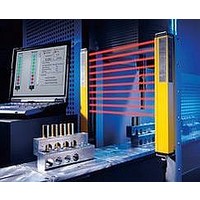
Light Curtain Type
Safety
Lead Free Status / RoHS Status
Contains lead / RoHS non-compliant
Lead Free Status / RoHS Status
Contains lead / RoHS non-compliant


Courtesy of Steven Engineering, Inc.-230 Ryan Way, South San Francisco, CA 94080-6370-Main Office: (650) 588-9200-Outside Local Area: (800) 258-9200-www.stevenengineering.com
Characteristics
* The measurement locations are the same as for the dielectric strength.
Engineering Data
Detection Ranges
Note: The graph contains typical data collected in a standard testing environment. These figures
Internal Connection Diagram
D40B-J1
Item
Contact resistance
Auxiliary output ON resistance
Response time
Insulation resistance *
Dielectric
strength
Vibration resistance
Shock resistance
Durability
Minimum rated current for safety contacts
Ambient operating temperature
Ambient operating humidity
Mounting method
Terminal screw tightening torque
Weight
16
14
12
10
8
6
4
2
0
are not guaranteed operating values. The actual operation distance may vary due to the
effects of nearby metals, magnetic materials, and ambient temperature.
Standard Sensor
−6
Distance from the target mark on the switch X (mm)
−4
Between output poles
Between inputs and outputs
Between power supply and
outputs
Mechanical
Electrical
−2
http://www.ia.omron.com/
2
3
Control circuit
0
1
4
A1
A2
2
X1
OFF
ON
X2
4
13
14
MOS-FET
6
output
21
NC
22
Model
16
14
12
10
8
6
4
2
0
−6
Elongated Sensor
Distance from the target mark on the switch X (mm)
100 m max.
(not including auxiliary output)
36
25 ms max.
100 M min. (at 500 VDC)
1,500 VAC 1 min.
10 to 55 to 10 Hz, 1 mm single amplitude (double amplitude: 2 mm), IEC68-2-6
300 m/s
1,000,000 operations min.
100,000 operation min. (at the rated load)
10 VAC/VDC, 10 mA (reference values)
90% at +50°C
35 mm DIN Track (Screw mounting is not possible.)
1 N·m
147 g
10 to +55°C
−4
(nominal value)
2
−2
D40B-J1
0
D40B-J2
Note: 1. If a 100/230 VAC power supply is used, connect it to the A1
2
OFF
2. If a 24 VDC power supply is used, connect it to the + and
ON
(c)Copyright OMRON Corporation 2007 All Rights Reserved.
and A2 terminals. Do not connect the power supply to the +
and
terminals. Do not connect the power supply to the A1 and
A2 terminals.
4
6
2
3
terminals.
1
4
Control circuit
A1
A2
25
20
15
10
Sensing
surface
5
0
100 m
(including auxiliary output)
590 g
High-temperature Type Sensor
−6
X
Distance from the target mark on the switch X (mm)
+
−
Target mark
Y
−4
X1
max.
X2
−2
13
14
D40B-J2
23
24
0
---
31
32
2
4
D40B
OFF
ON
6
4
Related parts for F39-EU1E
Image
Part Number
Description
Manufacturer
Datasheet
Request
R

Part Number:
Description:
Pair Of Flat Mounting Brackets (transmitter & Receiver)
Manufacturer:
Omron
Part Number:
Description:
Pair Of Protective Shrouds (transmitter & Receiver)
Manufacturer:
Omron

Part Number:
Description:
G6S-2GLow Signal Relay
Manufacturer:
Omron Corporation
Datasheet:
Part Number:
Description:
Compact, Low-cost, SSR Switching 5 to 20 A
Manufacturer:
Omron Corporation
Datasheet:
Part Number:
Description:
Manufacturer:
Omron Corporation
Datasheet: