F39-EU1E Omron, F39-EU1E Datasheet - Page 75
F39-EU1E
Manufacturer Part Number
F39-EU1E
Description
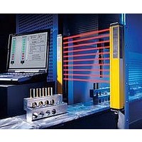
F3S-B OPTIONAL PROGRAMMING KIT
Manufacturer
Omron
Datasheet
1.F39-EU1E.pdf
(865 pages)
Specifications of F39-EU1E
Leaded Process Compatible
No
Peak Reflow Compatible (260 C)
No
Light Curtain Type
Safety
Lead Free Status / RoHS Status
Contains lead / RoHS non-compliant
Lead Free Status / RoHS Status
Contains lead / RoHS non-compliant


Courtesy of Steven Engineering, Inc.-230 Ryan Way, South San Francisco, CA 94080-6370-Main Office: (650) 588-9200-Outside Local Area: (800) 258-9200-www.stevenengineering.com
➌-➁-5 Preventing Surges when the Coil Is Turned OFF
Counter electromotive force generated from a coil when the coil is
turned OFF causes damage to semiconductor elements and faulty
operation.
As a countermeasure, install surge absorbing circuits at both ends of
the coil. When surge absorbing circuits have been installed, the Relay
release time will be lengthened, so be sure to check operation using
the actual circuits.
External surges must be taken into account for the repetitive peak
reverse voltage and the DC reverse voltage, and a diode with
sufficient capacity used. Also, ensure that the diode has an average
rectified current that is greater than the coil current.
Do not use under conditions in which a surge is included in the power
supply, such as when an inductive load is connected in parallel to the
coil. Doing so will cause damage to the installed (or built-in) coil surge
absorbing diode.
➌-➁-6 Leakage Current to Relay Coils
Do not allow leakage current to flow to Relay coils. Construct a
corrective circuit as shown in examples 1 and 2 below.
Example: Circuit with Leakage Current Occurring
Corrective Example 1
Corrective Example 2:
When an Output Value Is Required in the Same Phase as the
Input Value
➌-➁-7 Using with Infrequent Switching
For operations using a microload and infrequent switching,
periodically perform continuity tests on the contacts. When switching
is not executed for contacts for long periods of time, it causes contact
instability due to factors such as the formation of film on contact
surfaces.
The frequency with which the inspections are needed will depend on
factors such as the operating environment and the type of load.
http://www.ia.omron.com/
I
O
TE
Correct
Incorrect
Correct
➌-➁-8 Configuring Sequence Circuits
When configuring a sequence circuit, care must be taken to ensure
that abnormal operation does not occur due to faults such as sneak
current.
The following diagram shows an example of sneak current. After
contacts A, B, and C are closed causing Relays X
operate, and then contacts B and C are opened, a series circuit is
created from A to X
not release.
The following diagram shows an example of a circuit that corrects the
above problem. Also, in a DC circuit, the sneak current can be
prevented by means of a diode.
➌-➁-9 Connecting Relay Grounds
Do not connect a ground when using a Relay at high temperatures or
high humidity. Depending on the grounding method, electrolytic
corrosion may occur, causing the wire to the coil to sever. If the Relay
must be grounded, use the method shown in the following diagrams.
(1) Ground the positive side of the power supply. (Fig. 1 and Fig. 2)
(2) If grounding the positive side of the power supply is not possible
(3) Do not ground the negative side and connect a switch to the
➌-➁-10 Individual Specifications for Must-operate/
If it is necessary to know the individual specifications of
characteristics, such as must-operate voltages, must-release
voltages, operate times, and release times, please contact your
OMRON representative.
and the negative side must be grounded, connect a switch at the
positive side so that the coil is connected to the negative side.
(Fig. 3)
negative side.
This will cause electrolytic corrosion to occur. (Fig. 4)
(c)Copyright OMRON Corporation 2007 All Rights Reserved.
Fig. 1
Fig. 3
release Voltages and Operate/Release Times
1
to X
C
C
A
A
X
X
1
Correct
Correct
1
2
to X
B
B
X
X
3
2
2
. This causes the Relay to hum or to
Precautions for All Relays
D
X
X
3
3
Difference in electric potential
Incorrect
Correct
Fig. 2
Fig. 4
1
, X
2
, and X
Incorrect
Correct
3
to
C-8
Related parts for F39-EU1E
Image
Part Number
Description
Manufacturer
Datasheet
Request
R

Part Number:
Description:
Pair Of Flat Mounting Brackets (transmitter & Receiver)
Manufacturer:
Omron
Part Number:
Description:
Pair Of Protective Shrouds (transmitter & Receiver)
Manufacturer:
Omron

Part Number:
Description:
G6S-2GLow Signal Relay
Manufacturer:
Omron Corporation
Datasheet:
Part Number:
Description:
Compact, Low-cost, SSR Switching 5 to 20 A
Manufacturer:
Omron Corporation
Datasheet:
Part Number:
Description:
Manufacturer:
Omron Corporation
Datasheet: