HGT1S7N60C3DS Fairchild Semiconductor, HGT1S7N60C3DS Datasheet - Page 3
HGT1S7N60C3DS
Manufacturer Part Number
HGT1S7N60C3DS
Description
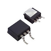
IGBT UFS N-CH 600V 14A TO-263AB
Manufacturer
Fairchild Semiconductor
Datasheet
1.HGT1S7N60C3DS9A.pdf
(9 pages)
Specifications of HGT1S7N60C3DS
Voltage - Collector Emitter Breakdown (max)
600V
Vce(on) (max) @ Vge, Ic
2V @ 15V, 7A
Current - Collector (ic) (max)
14A
Power - Max
60W
Input Type
Standard
Mounting Type
Surface Mount
Package / Case
D²Pak, TO-263 (2 leads + tab)
Channel Type
N
Configuration
Single
Collector-emitter Voltage
600V
Collector Current (dc) (max)
14A
Gate To Emitter Voltage (max)
±20V
Pin Count
2 +Tab
Mounting
Surface Mount
Operating Temperature (min)
-40C
Operating Temperature (max)
150C
Operating Temperature Classification
Automotive
Lead Free Status / RoHS Status
Lead free / RoHS Compliant
Igbt Type
-
Lead Free Status / Rohs Status
Compliant
Available stocks
Company
Part Number
Manufacturer
Quantity
Price
Company:

Part Number:
HGT1S7N60C3DS
Manufacturer:
FAIRCHILD
Quantity:
12 500
Company:
Part Number:
HGT1S7N60C3DS9A
Manufacturer:
FSC
Quantity:
2 400


HGTP7N60C3D, HGT1S7N60C3DS, HGT1S7N60C3D
Rev. B 1
Electrical Characteristics
Off Characteristics
On Characteristics
Switching Characteristics
Drain-Source Diode Characteristics and Maximum Ratings
NOTES:
ending at the point where the collector current equals zero (I
standard No. 24-1 Method for Measurement of Power Device Turn-Off Switching Loss. This test method produces the true total Turn-Off
Energy Loss. Turn-On losses include diode losses.
BV
I
I
V
V
SSOA
V
t
t
t
t
E
E
Q
V
t
CES
GES
d(ON)I
rI
d(OFF)I
fI
rr
3.Turn-Off Energy Loss (E
CE(SAT)
GE(TH)
GEP
ON
OFF
EC
Symbol
G(ON)
CES
Current Turn-On Delay Time
Current Rise Time
Current Turn-Off Delay Time
Current Fall Time
Turn-On Energy
Turn-Off Energy (Note 3)
On-State Gate Charge
Diode Forward Voltage
Diode Reverse Recovery Time
Collector to Emitter Breakdown Voltage I
Collector to Emitter Leakage Current
Gate-Emitter Leakage Current
Collector to Emitter Saturation Voltage
Gate-Emitter Threshold Voltage
Switching SOA
Gate to Emitter Plateau Voltage
OFF
) is defined as the integral of the instantaneous power loss starting at the trailing edge of the input pulse and
Parameter
T
A
= 25°C unless otherwise noted
T
I
V
V
R
L = 1mH
I
V
I
I
I
CE
C
EC
EC
EC
J
CE(PK)
GE
CE
CE
G
= I
= 150
V
V
V
I
V
I
T
T
R
V
L = 1mH
I
= 50Ω
= I
= 7A
= 7A, dI
= 1A, dI
C
C
C
C
= 0A). The HGTP7N60C3D and HGT1S7N60C3DS were tested per JEDEC
= 0.5 BV
= 15V
C
J
GE
CE
CE
GE
GE
G
C110
= 250µA, V
= I
= 250µA, V
= I
= 150
C110
= 25
= 50Ω ,
= BV
= BV
= 15V,
= 0.8 BV
= ±25V
= 15V
C110
C110
o
3
,
C
Test Conditions
o
EC
EC
o
C
, V
,
C,
CES
CES
CES
/dt = 200A/µs
/dt = 200A/µs
CE
, T
, T
CES
CE
GE
V
V
V
V
= 0.5 BV
C
C
CE(PK)
CE(PK)
GE
GE
= V
= 0V
= 25
= 150
T
T
= 15V
= 20V
GE
C
C
o
= 25
= 150
,
= 480V
= 600V
C
o
CES
C
o
C
o
C
-
-
-
-
-
-
-
-
-
-
-
600
Min
3.0
40
60
-
-
-
-
-
11.5
350
140
165
600
1.9
8.5
25
18
23
30
Typ
1.6
1.9
5.0
8
-
-
-
-
-
www.fairchildsemi.com
400
275
2.5
37
30
30
38
±250
Max
-
-
-
-
250
6.0
2.0
2.0
2.4
-
-
-
-
Units
mA
nC
nC
ns
ns
µA
ns
ns
ns
ns
µJ
µJ
nA
V
V
A
A
V
V
V
V
Related parts for HGT1S7N60C3DS
Image
Part Number
Description
Manufacturer
Datasheet
Request
R

Part Number:
Description:
Fairchild Semiconductor [IGBT MODULE]
Manufacturer:
Fairchild Semiconductor
Datasheet:

Part Number:
Description:
Discrete Semiconductor Modules
Manufacturer:
Fairchild Semiconductor
Part Number:
Description:
Discrete Semiconductor Modules
Manufacturer:
Fairchild Semiconductor
Part Number:
Description:
This N-Channel MOSFET is produced using Fairchild Semiconductor’s advanced Power Trench® process
Manufacturer:
Fairchild Semiconductor
Datasheet:
Part Number:
Description:
This N-Channel MOSFET is produced using Fairchild Semiconductor’s advanced Power Trench® process
Manufacturer:
Fairchild Semiconductor
Datasheet:
Part Number:
Description:
This N-Channel MOSFET is produced using Fairchild Semiconductor’s advanced PowerTrench® process
Manufacturer:
Fairchild Semiconductor
Datasheet:
Part Number:
Description:
This N-Channel MOSFET is produced using Fairchild Semiconductor’s advanced PowerTrench® process
Manufacturer:
Fairchild Semiconductor
Datasheet:
Part Number:
Description:
This N-Channel MOSFET is produced using Fairchild Semiconductor’s advanced Power Trench® process
Manufacturer:
Fairchild Semiconductor
Datasheet:
Part Number:
Description:
This N-Channel logic Level MOSFETs are produced using Fairchild Semiconductor‘s advanced Power Trench® process that has been special tailored to minimize the on-state resistance and yet maintain superior switching performance
Manufacturer:
Fairchild Semiconductor
Datasheet:
Part Number:
Description:
This N-Channel MOSFET is produced using Fairchild Semiconductor’s advanced Power Trench® process
Manufacturer:
Fairchild Semiconductor
Datasheet:
Part Number:
Description:
This N-Channel SyncFET™ is produced using Fairchild Semiconductor’s advanced PowerTrench® process
Manufacturer:
Fairchild Semiconductor
Datasheet:
Part Number:
Description:
This N-Channel SyncFET™ is produced using Fairchild Semiconductor’s advanced PowerTrench® process
Manufacturer:
Fairchild Semiconductor
Datasheet:
Part Number:
Description:
This N-Channel SyncFET™ is produced using Fairchild Semiconductor’s advanced PowerTrench® process
Manufacturer:
Fairchild Semiconductor
Datasheet:
Part Number:
Description:
This N-Channel logic Level MOSFETs are produced using Fairchild Semiconductor‘s advanced Power Trench® process that has been special tailored to minimize the on-state resistance and yet maintain superior switching performance
Manufacturer:
Fairchild Semiconductor
Datasheet:
Part Number:
Description:
This N-Channel MOSFET is produced using Fairchild Semiconductor’s advanced Power Trench® process that has been especially tailored to minimize the on-state resistance and yet maintain superior switching performance
Manufacturer:
Fairchild Semiconductor
Datasheet: