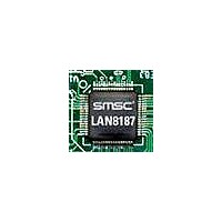
LAN8187-JT SMSC, LAN8187-JT Datasheet - Page 13

LAN8187-JT
Manufacturer Part Number
LAN8187-JT
Description
Ethernet ICs HiPerfrm Ethrnt PHY
Manufacturer
SMSC
Type
MII/RMII Ethernet Transceiverr
Datasheet
1.LAN8187-JT.pdf
(78 pages)
Specifications of LAN8187-JT
Ethernet Connection Type
10 Base-T, 100 Base-TX
Minimum Operating Temperature
0 C
Mounting Style
SMD/SMT
Product
Ethernet Transceivers
Number Of Transceivers
1
Standard Supported
802.3ab
Data Rate
10 MB, 100 MB
Supply Voltage (max)
3.3 V
Supply Voltage (min)
1.8 V
Supply Current (max)
39 mA, 81.6 mA
Maximum Operating Temperature
+ 70 C
Package / Case
TQFP-64
Lead Free Status / RoHS Status
Lead free / RoHS Compliant
Available stocks
Company
Part Number
Manufacturer
Quantity
Price
Company:
Part Number:
LAN8187-JT
Manufacturer:
Standard
Quantity:
1 040
Company:
Part Number:
LAN8187-JT
Manufacturer:
STM
Quantity:
5 362
Part Number:
LAN8187-JT
Manufacturer:
SMSC
Quantity:
20 000
±15kV ESD Protected MII/RMII 10/100 Ethernet Transceiver with HP Auto-MDIX & flexPWR
Datasheet
SMSC LAN8187/LAN8187i
SIGNAL NAME
COL/CRS_DV
nINTSEL
RX_CLK
RX_ER/
RXD3/
RXD0
RXD1
RXD2
RXD4
TYPE
Table 3.1 MII Signals (continued)
I/O
O
O
O
O
O
O
DATASHEET
Receive Data 0: Bit 0 of the 4 data bits that are sent by the PHY
in the receive path.
Receive Data 1: Bit 1 of the 4 data bits that are sent by the PHY
in the receive path.
Receive Data 2: Bit 2 of the 4 data bits that sent by the PHY in
the receive path.
Note:
Receive Data 3: Bit 3 of the 4 data bits that sent by the PHY in
the receive path.
nINTSEL: On power-up or external reset, the mode of the
nINT/TXER/TXD4 pin is selected.
Notes:
Receive Error: Asserted to indicate that an error was detected
somewhere in the frame presently being transferred from the
PHY.
MII Receive Data 4: In Symbol Interface (5B Decoding) mode,
this signal is the MII Receive Data 4 signal, the MSB of the
received 5-bit symbol code-group. Unless configured in this
mode, the pin functions as RX_ER.
Notes:
Receive Clock: 25MHz in 100Base-TX mode. 2.5MHz in
10Base-T mode.
Notes:
MII Collision Detect: Asserted to indicate detection of collision
condition.
RMII CRS_DV (Carrier Sense/Receive Data Valid) Asserted to
indicate when the receive medium is non-idle. When a 10BT
packet is received, CRS_DV is asserted, but RXD[1:0] is held
low until the SFD byte (10101011) is received. In 10BT, half-
duplex mode, transmitted data is not looped back onto the
receive data pins, per the RMII standard.
Note:
When floated or pulled to VDDIO, nINT is selected (default).
When pulled low to VSS through a Pull-down resistor (see
Table 4.4, “Boot Strapping Configuration Resistors,” on
page
RXD3 is not used in RMII Mode
If the nINT/TXER/TXD4 pin is configured for nINT mode, it
needs a pull-up resistor to VDDIO.
See
page 32
options.
This pin has an internal pull-down resistor, and must not be
high during reset. The RX_ER signal is optional in RMII Mode.
This signal is not used in RMII Mode
Section 4.10, "(TX_ER/TXD4)/nINT Strapping," on
13
33), TXER/TXD4 is selected.
This signal is not used in RMII Mode.
See
page 26
®
for additional information on configuration/strapping
Technology
Section 4.6.3, "MII vs. RMII Configuration," on
for more details.
DESCRIPTION
Revision 1.7 (03-04-11)


