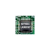
LAN8187-JT SMSC, LAN8187-JT Datasheet - Page 55

LAN8187-JT
Manufacturer Part Number
LAN8187-JT
Description
Ethernet ICs HiPerfrm Ethrnt PHY
Manufacturer
SMSC
Type
MII/RMII Ethernet Transceiverr
Datasheet
1.LAN8187-JT.pdf
(78 pages)
Specifications of LAN8187-JT
Ethernet Connection Type
10 Base-T, 100 Base-TX
Minimum Operating Temperature
0 C
Mounting Style
SMD/SMT
Product
Ethernet Transceivers
Number Of Transceivers
1
Standard Supported
802.3ab
Data Rate
10 MB, 100 MB
Supply Voltage (max)
3.3 V
Supply Voltage (min)
1.8 V
Supply Current (max)
39 mA, 81.6 mA
Maximum Operating Temperature
+ 70 C
Package / Case
TQFP-64
Lead Free Status / RoHS Status
Lead free / RoHS Compliant
Available stocks
Company
Part Number
Manufacturer
Quantity
Price
Company:
Part Number:
LAN8187-JT
Manufacturer:
Standard
Quantity:
1 040
Company:
Part Number:
LAN8187-JT
Manufacturer:
STM
Quantity:
5 362
Part Number:
LAN8187-JT
Manufacturer:
SMSC
Quantity:
20 000
±15kV ESD Protected MII/RMII 10/100 Ethernet Transceiver with HP Auto-MDIX & flexPWR
Datasheet
SMSC LAN8187/LAN8187i
5.4.8.3
5.4.9
5.4.9.1
Ethernet
10/100
MAC
Ethernet
10/100
MAC
Note: This special test mode is only available when operating in RMII mode.
Connector Loopback
The LAN8187/LAN8187i maintains reliable transmission over very short cables, and can be tested in
a connector loopback as shown in
transmit signals an the output of the transformer back to the receiver inputs, and this loopback will
work at both 10 and 100.
Configuration Signals
The PHY has 11 configuration signals whose inputs should be driven continuously, either by external
logic or external pull-up/pull-down resistors.
Physical Address Bus - PHYAD[4:0]
The PHYAD[4:0] signals are driven high or low to give each PHY a unique address. This address is
latched into an internal register at end of hardware reset. In a multi-PHY application (such as a
repeater), the controller is able to manage each PHY via the unique address. Each PHY checks each
management data frame for a matching address in the relevant bits. When a match is recognized, the
PHY responds to that particular frame. The PHY address is also used to seed the scrambler. In a multi-
TXD
RXD
TXD
RXD
X
X
Digital
Ethernet Transceiver
Digital
Figure 5.4 Connector Loopback Block Diagram
Ethernet Transceiver
Figure 5.3 Far Loopback Block Diagram
Far-end system
SMSC
SMSC
Analog
Analog
DATASHEET
Figure
55
5.4. An RJ45 loopback cable can be used to route the
®
Technology
TX
RX
TX
RX
XFMR
XFMR
RJ45 Loopback Cable.
Created by connecting pin 1 to pin 3
and connecting pin 2 to pin 6.
CAT-5
1
2
3
4
5
6
7
8
Revision 1.7 (03-04-11)
Partner
Link


