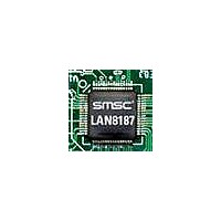
LAN8187-JT SMSC, LAN8187-JT Datasheet - Page 49

LAN8187-JT
Manufacturer Part Number
LAN8187-JT
Description
Ethernet ICs HiPerfrm Ethrnt PHY
Manufacturer
SMSC
Type
MII/RMII Ethernet Transceiverr
Datasheet
1.LAN8187-JT.pdf
(78 pages)
Specifications of LAN8187-JT
Ethernet Connection Type
10 Base-T, 100 Base-TX
Minimum Operating Temperature
0 C
Mounting Style
SMD/SMT
Product
Ethernet Transceivers
Number Of Transceivers
1
Standard Supported
802.3ab
Data Rate
10 MB, 100 MB
Supply Voltage (max)
3.3 V
Supply Voltage (min)
1.8 V
Supply Current (max)
39 mA, 81.6 mA
Maximum Operating Temperature
+ 70 C
Package / Case
TQFP-64
Lead Free Status / RoHS Status
Lead free / RoHS Compliant
Available stocks
Company
Part Number
Manufacturer
Quantity
Price
Company:
Part Number:
LAN8187-JT
Manufacturer:
Standard
Quantity:
1 040
Company:
Part Number:
LAN8187-JT
Manufacturer:
STM
Quantity:
5 362
Part Number:
LAN8187-JT
Manufacturer:
SMSC
Quantity:
20 000
±15kV ESD Protected MII/RMII 10/100 Ethernet Transceiver with HP Auto-MDIX & flexPWR
Datasheet
SMSC LAN8187/LAN8187i
5.3
5.3.1
Mask
ADDRESS
30.7
30.6
31.9:7
31.4:2
31.6
31.5
31.1
31.0
29.7
29.6
The Management interface supports an interrupt capability that is not a part of the IEEE 802.3
specification. It generates an active low asynchronous interrupt signal on the nINT output whenever
certain events are detected as setup by the Interrupt Mask Register 30.
The Interrupt system on the SMSC LAN8187/8187i has two modes, a Primary Interrupt mode and an
Alternative Interrupt mode. Both systems will assert the nINT pin low when the corresponding mask
bit is set, the difference is how they de-assert the output interrupt signal nINT.
The Primary interrupt mode is the default interrupt mode after a power-up or hard reset, the Alternative
interrupt mode would need to be setup again after a power-up or hard reset.
Primary Interrupt System
The Primary Interrupt system is the default interrupt mode, (Bit 17.6 = ‘0’). The Primary Interrupt
System is always selected after power-up or hard reset.
To set an interrupt, set the corresponding mask bit in the interrupt Mask register 30 (see
Then when the event to assert nINT is true, the nINT output will be asserted.
When the corresponding Event to De-Assert nINT is true, then the nINT will be de-asserted.
Interrupt Management
Interrupt Source Flag
Scramble Disable
Speed Indication
Enable 4B5B
Auto-Negotiation
Reserved
Reserved
GPO[2:0]
ENERGYON
NAME
complete
Table 5.45 Register 31 - PHY Special Control/Status (continued)
General Purpose Output connected to signals
HCDSPEED value:
GPO[2:0]
0 = Bypass encoder/decoder.
1 = enable 4B5B encoding/decoding.
MAC Interface must be configured in MII mode.
Write as 0, ignore on Read.
[001]=10Mbps Half-duplex
[101]=10Mbps Full-duplex
[010]=100Base-TX Half-duplex
[110]=100Base-TX Full-duplex
Write as 0; ignore on Read
0 = enable data scrambling
1 = disable data scrambling,
Table 5.46 Interrupt Management Table.
17.1
1.5
Interrupt Source
DATASHEET
Auto-Negotiate
ENERGYON
Complete
DESCRIPTION
49
®
Technology
Event to Assert nINT
Rising 17.1
Rising 1.5
a
Event to De-Assert nINT
MODE
Reading register 29
Reading register 29
Revision 1.7 (03-04-11)
RW
RW
RW
RW
RW
RO
Falling 17.1 or
Falling 1.5 or
DEFAULT
Table
000
0
1
0
0
0
5.46).


