HUFA76439S3S Fairchild Semiconductor, HUFA76439S3S Datasheet
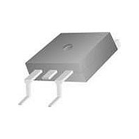
MOSFET N-CH 60V 75A D2PAK

HUFA76439S3S

Manufacturer Part Number
HUFA76439S3S
Description
MOSFET N-CH 60V 75A D2PAK
Manufacturer
Fairchild Semiconductor
Series
UltraFET™r
Datasheet

Specifications of HUFA76439S3S

Fet Type
MOSFET N-Channel, Metal Oxide
Fet Feature
Logic Level Gate
Rds On (max) @ Id, Vgs
12 mOhm @ 75A, 10V
Drain To Source Voltage (vdss)
60V
Current - Continuous Drain (id) @ 25° C
75A
Vgs(th) (max) @ Id
3V @ 250µA
Gate Charge (qg) @ Vgs
84nC @ 10V
Input Capacitance (ciss) @ Vds
2745pF @ 25V
Power - Max
155W
Mounting Type
Surface Mount
Package / Case
D²Pak, TO-263 (2 leads + tab)
Configuration
Single
Transistor Polarity
N-Channel
Resistance Drain-source Rds (on)
0.01 Ohms
Forward Transconductance Gfs (max / Min)
0.008 S
Drain-source Breakdown Voltage
60 V
Gate-source Breakdown Voltage
+/- 16 V
Continuous Drain Current
71 A
Power Dissipation
155 W
Maximum Operating Temperature
+ 175 C
Mounting Style
SMD/SMT
Minimum Operating Temperature
- 55 C
Lead Free Status / RoHS Status
Lead free / RoHS Compliant

Available stocks

Company
Part Number
Manufacturer
Quantity
Price
Part Number:
HUFA76439S3S
Manufacturer:
FAIRCHILD
Quantity:
12 500
©2002 Fairchild Semiconductor Corporation
71A, 60V, 0.014 Ohm, N-Channel, Logic
Level UltraFET® Power MOSFET
Packaging
Symbol
Absolute Maximum Ratings
This product has been designed to meet the extreme test conditions and environment demanded by the automotive industry. For a copy
All Fairchild semiconductor products are manufactured, assembled and tested under ISO9000 and QS9000 quality systems certification.
Drain to Source Voltage (Note 1). . . . . . . . . . . . . . . . . . . . . . . . . . . . . . . . . . . . . . . . . .V
Drain to Gate Voltage (R
Gate to Source Voltage . . . . . . . . . . . . . . . . . . . . . . . . . . . . . . . . . . . . . . . . . . . . . . . . . .V
Drain Current
Pulsed Avalanche Rating . . . . . . . . . . . . . . . . . . . . . . . . . . . . . . . . . . . . . . . . . . . . . . . . UIS
Power Dissipation . . . . . . . . . . . . . . . . . . . . . . . . . . . . . . . . . . . . . . . . . . . . . . . . . . . . . . . P
Operating and Storage Temperature . . . . . . . . . . . . . . . . . . . . . . . . . . . . . . . . . . . . T
Maximum Temperature for Soldering
NOTES:
CAUTION: Stresses above those listed in “Absolute Maximum Ratings” may cause permanent damage to the device. This is a stress only rating and operation of the
device at these or any other conditions above those indicated in the operational sections of this specification is not implied.
1. T
Continuous (T
Continuous (T
Continuous (T
Continuous (T
Pulsed Drain Current . . . . . . . . . . . . . . . . . . . . . . . . . . . . . . . . . . . . . . . . . . . . . . . . . . I
Derate Above 25
Leads at 0.063in (1.6mm) from Case for 10s. . . . . . . . . . . . . . . . . . . . . . . . . . . . . . . . . T
Package Body for 10s, See Techbrief TB334. . . . . . . . . . . . . . . . . . . . . . . . . . . . . . . T
J
= 25
JEDEC TO-220AB
HUFA76439P3
o
C to 150
C
C
C
C
(FLANGE)
DRAIN
Reliability data can be found at: http://www.fairchildsemi.com/products/discrete/reliability/index.html.
= 25
= 25
= 100
= 100
o
C . . . . . . . . . . . . . . . . . . . . . . . . . . . . . . . . . . . . . . . . . . . . . . . . . . . . . .
o
SOURCE
C.
o
o
C, V
C, V
o
o
GS
G
C, V
C, V
DRAIN
= 20k ) (Note 1) . . . . . . . . . . . . . . . . . . . . . . . . . . . . . . . V
GS
GS
GATE
GS
GS
= 5V) . . . . . . . . . . . . . . . . . . . . . . . . . . . . . . . . . . . . . . . .I
= 10V) (Figure 2) . . . . . . . . . . . . . . . . . . . . . . . . . . . . . . .I
= 5V) . . . . . . . . . . . . . . . . . . . . . . . . . . . . . . . . . . . . . . .I
= 4.5V) (Figure 2) . . . . . . . . . . . . . . . . . . . . . . . . . . . . . .I
D
S
of the requirements, see AEC Q101 at: http://www.aecouncil.com/
SOURCE
GATE
T
Data Sheet
C
= 25
JEDEC TO-263AB
HUFA76439S3S
o
C, Unless Otherwise Specified
(FLANGE)
DRAIN
HUFA76439P3, HUFA76439S3S
Features
• Ultra Low On-Resistance
• Simulation Models
• Peak Current vs Pulse Width Curve
• UIS Rating Curve
• Switching Time vs R
Ordering Information
NOTE: When ordering, use the entire part number. Add the suffix T
to obtain the variant in tape and reel, e.g., HUFA76439S3ST.
HUFA76439P3
HUFA76439S3S
- r
- r
- Temperature Compensated PSPICE® and SABER™
- Spice and SABER Thermal Impedance Models
- www.fairchildsemi.com
PART NUMBER
Electrical Models
J
DS(ON)
DS(ON)
, T
DGR
DSS
STG
DM
pkg
GS
D
D
D
D
D
L
= 0.012
= 0.014
July 2002
HUFA76439P3, HUFA76439S3S
TO-220AB
TO-263AB
GS
Figures 6, 17, 18
V
V
PACKAGE
GS
GS
-55 to 175
Curves
Figure 4
1.04
155
300
260
60
60
71
75
50
48
16
10V
5V
HUFA76439P3, HUFA76439S3S Rev. B1
76439P
76439S
BRAND
UNITS
W/
o
o
o
W
V
V
V
A
A
A
A
C
C
C
o
C

Related parts for HUFA76439S3S

HUFA76439S3S Summary of contents

Page 1

... UIS Rating Curve • Switching Time vs R Ordering Information PART NUMBER HUFA76439P3 HUFA76439S3S NOTE: When ordering, use the entire part number. Add the suffix T to obtain the variant in tape and reel, e.g., HUFA76439S3ST Unless Otherwise Specified DSS DGR , T J STG July 2002 = 0 ...

Page 2

... MIN TYP (Figure 12 0.010 - 0.0117 - 0.0125 - - - - - - - 16 - 300 - 29 - 105 - - - - - 11 - 125 - 45 - 125 - - = 30V 1.0mA - 2 2745 - 840 - 145 MIN TYP - - - - - - - - HUFA76439P3, HUFA76439S3S Rev. B1 MAX UNITS - 250 A 100 0.012 0.014 0.015 o 0.96 C C/W 470 200 ns 205 255 MAX UNITS 1. 140 nC ...

Page 3

... FIGURE 2. MAXIMUM CONTINUOUS DRAIN CURRENT RECTANGULAR PULSE DURATION ( PULSE WIDTH (s) FIGURE 4. PEAK CURRENT CAPABILITY V = 10V 4. 100 125 150 CASE TEMPERATURE ( C) C CASE TEMPERATURE NOTES: DUTY FACTOR PEAK FOR TEMPERATURES o ABOVE 25 C DERATE PEAK CURRENT AS FOLLOWS: 175 - 150 - HUFA76439P3, HUFA76439S3S Rev. B1 175 ...

Page 4

... PULSE DURATION = DUTY CYCLE = 0.5% MAX DRAIN TO SOURCE VOLTAGE (V) DS FIGURE 8. SATURATION CHARACTERISTICS 2.5 PULSE DURATION = 80 s DUTY CYCLE = 0.5% MAX 2.0 1.5 1.0 0.5 -80 - JUNCTION TEMPERATURE ( J RESISTANCE vs JUNCTION TEMPERATURE HUFA76439P3, HUFA76439S3S Rev +1] DSS 10V = 3. 10V 75A GS D 120 160 200 o C) ...

Page 5

... A D 1.1 1.0 0.9 -80 - JUNCTION TEMPERATURE ( J VOLTAGE vs JUNCTION TEMPERATURE V = 30V WAVEFORMS IN DESCENDING ORDER GATE CHARGE (nC) g GATE CURRENT V = 10V 30V 75A GATE TO SOURCE RESISTANCE ( ) GS FIGURE 16. SWITCHING TIME vs GATE RESISTANCE HUFA76439P3, HUFA76439S3S Rev. B1 120 160 160 200 50A = 25A d(OFF d(ON ...

Page 6

... FIGURE 21. SWITCHING TIME TEST CIRCUIT ©2002 Fairchild Semiconductor Corporation DUT 0. DUT g(REF DUT DSS FIGURE 18. UNCLAMPED ENERGY WAVEFORMS Q g(TOT g( g(TH FIGURE 20. GATE CHARGE WAVEFORMS d(ON 90% 10% 50% PULSE WIDTH FIGURE 22. SWITCHING TIME WAVEFORM HUFA76439P3, HUFA76439S3S Rev 10V GS t OFF d(OFF 90% 10% 90% 50% ...

Page 7

... Fairchild Semiconductor Corporation DPLCAP 10 RSLC2 - 6 ESG 8 EVTHRES + - + 19 LGATE EVTEMP 8 RGATE - + RLGATE CIN S1A S2A S1B S2B EGS EDS LDRAIN 5 RLDRAIN RSLC1 DBREAK ESLC DBODY RDRAIN EBREAK MWEAK MMED MSTRO LSOURCE 8 7 RSOURCE RLSOURCE RBREAK 17 18 RVTEMP VBAT RVTHRES HUFA76439P3, HUFA76439S3S Rev. B1 DRAIN 2 SOURCE 3 ...

Page 8

... LGATE EVTEMP GATE RGATE - + RLGATE S1A S2A S1B S2B EGS RSLC1 RDBREAK 51 72 ISCL DBREAK 50 71 RDRAIN MWEAK 8 EBREAK MMED + MSTRO CIN 8 7 RSOURCE RLSOURCE RBREAK RVTEMP EDS + RVTHRES HUFA76439P3, HUFA76439S3S Rev. B1 LDRAIN DRAIN 2 RLDRAIN RDBODY DBODY LSOURCE SOURCE 3 VBAT ...

Page 9

... Fairchild Semiconductor Corporation JUNCTION th RTHERM1 CTHERM1 6 RTHERM2 CTHERM2 5 RTHERM3 CTHERM3 4 RTHERM4 CTHERM4 3 RTHERM5 CTHERM5 2 RTHERM6 CTHERM6 tl CASE HUFA76439P3, HUFA76439S3S Rev. B1 ...

Page 10

CROSSVOLT â â â â ...

Related keywords