IPB60R125CP Infineon Technologies, IPB60R125CP Datasheet
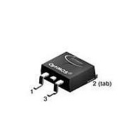
MOSFET N-CH 600V 25A TO263

IPB60R125CP

Manufacturer Part Number
IPB60R125CP
Description
MOSFET N-CH 600V 25A TO263
Manufacturer
Infineon Technologies
Series
CoolMOS™r
Datasheets

Specifications of IPB60R125CP

Package / Case
D²Pak, TO-263 (2 leads + tab)
Fet Type
MOSFET N-Channel, Metal Oxide
Fet Feature
Standard
Rds On (max) @ Id, Vgs
125 mOhm @ 16A, 10V
Drain To Source Voltage (vdss)
600V
Current - Continuous Drain (id) @ 25° C
25A
Vgs(th) (max) @ Id
3.5V @ 1.1mA
Gate Charge (qg) @ Vgs
70nC @ 10V
Input Capacitance (ciss) @ Vds
2500pF @ 100V
Power - Max
208W
Mounting Type
Surface Mount
Gate Charge Qg
53 nC
Minimum Operating Temperature
- 55 C
Configuration
Single
Transistor Polarity
N-Channel
Resistance Drain-source Rds (on)
0.125 Ohm @ 10 V
Drain-source Breakdown Voltage
600 V
Gate-source Breakdown Voltage
+/- 20 V
Continuous Drain Current
25 A
Power Dissipation
208000 mW
Maximum Operating Temperature
+ 150 C
Mounting Style
SMD/SMT
Continuous Drain Current Id
25A
Drain Source Voltage Vds
650V
On Resistance Rds(on)
125mohm
Rds(on) Test Voltage Vgs
10V
Threshold Voltage Vgs Typ
3V
Rohs Compliant
Yes
Lead Free Status / RoHS Status
Lead free / RoHS Compliant
Lead Free Status / RoHS Status
Lead free / RoHS Compliant, Lead free / RoHS Compliant
Other names
IPB60R125CP
IPB60R125CPTR
SP000297368

Available stocks

Company
Part Number
Manufacturer
Quantity
Price
Part Number:
IPB60R125CP
Manufacturer:
INFINEON
Quantity:
30 000
Part Number:
IPB60R125CP
Manufacturer:
INFINEON/英飞凌
Quantity:
20 000
Rev. 1.0
Features
• Lowest figure-of-merit R
• Ultra low gate charge
• Extreme dv/dt rated
• High peak current capability
• Qualified according to JEDEC
• Pb-free lead plating; RoHS compliant
CoolMOS CP is specially designed for:
• Hard switching topologies, for Server and Telecom
Maximum ratings, at T
Parameter
Continuous drain current
Pulsed drain current
Avalanche energy, single pulse
Avalanche energy, repetitive t
Avalanche current, repetitive t
MOSFET dv /dt ruggedness
Gate source voltage
Power dissipation
Operating and storage temperature
CoolMOS
Type
IPP60R125CP
TM
Power Transistor
2)
Package
PG-TO220
j
=25 °C, unless otherwise specified
ON
xQ
AR
AR
g
1)
2),3)
2),3)
for target applications
Symbol Conditions
Ordering Code
I
I
E
E
I
dv /dt
V
P
T
D
D,pulse
AR
j
AS
AR
GS
tot
, T
SP000088488
stg
T
T
T
I
I
V
static
AC (f >1 Hz)
T
D
D
page 1
C
C
C
C
DS
=11 A, V
=11 A, V
=25 °C
=100 °C
=25 °C
=25 °C
=0...480 V
DD
DD
=50 V
=50 V
Product Summary
V
R
Q
DS
DS(on),max
g,typ
Marking
6R125P
@ T
j,max
-55 ... 150
Value
708
±20
±30
208
1.2
25
16
82
11
50
PG-TO263
IPB60R125CP
0.125 Ω
650
53
Unit
A
mJ
A
V/ns
V
W
°C
V
nC
2007-02-06

Related parts for IPB60R125CP

IPB60R125CP Summary of contents

Page 1

... Ordering Code SP000088488 Symbol Conditions I T =25 ° =100 ° =25 °C D,pulse = = 2 2), =0...480 static >1 Hz =25 °C tot stg page 1 IPB60R125CP @ T 650 DS j,max 0.125 Ω DS(on),max 53 g,typ PG-TO263 Marking 6R125P Value 708 1 ±20 ±30 208 -55 ... 150 V nC Unit V/ °C 2007-02-06 ...

Page 2

... GS(th =600 DSS T =25 ° =600 =150 ° = GSS = = DS(on) T =25 ° = = =150 ° MHz, open drain G page 2 IPB60R125CP Value Unit V/ns Values Unit min. typ. max 0.6 K 260 °C 600 - - V 2 µ 100 nA 0.125 Ω - 0.11 - 0.30 - Ω ...

Page 3

... D t =3.3 Ω R d(off =400 plateau = =25 ° =400 /dt =100 A/µ rrm =400V, V < <T , identical low side and high side switch. peak (BR)DSS j jmax oss oss page 3 IPB60R125CP Values min. typ. max. - 2500 - - 120 - - 110 - - 300 - - 5 0.9 1.2 - 430 - , * while V ...

Page 4

... P parameter: D 0.5 0 0.1 0.05 0.02 0.01 single pulse - Rev. 1.0 2 Safe operating area I =f parameter 120 160 10 [° Typ. output characteristics I =f parameter: V 120 105 [s] p page 4 IPB60R125CP ); T =25 ° limited by on-state resistance 10 µs 100 µ [ =25 ° µ 2007-02-06 ...

Page 5

... T Rev. 1.0 6 Typ. drain-source on-state resistance R =f(I DS(on) parameter 0.4 5 0.2 4 Typ. transfer characteristics I =f parameter: T 120 80 40 typ 0 60 100 140 180 0 [°C] j page 5 IPB60R125CP ); T =150 ° 5 [ |>2 DS(on)max j C ° [ °150 10 2007-02-06 ...

Page 6

... Forward characteristics of reverse diode I =f parameter 120 V 400 [nC] 12 Drain-source breakdown voltage V =f(T BR(DSS) 700 660 620 580 540 100 140 180 -60 [°C] j page 6 IPB60R125CP j 25 °C, 98% 150 °C, 98% 25 °C 150 °C 0.5 1 1 =0. - 100 140 T [° 180 2007-02-06 ...

Page 7

... Typ. capacitances C =f MHz Ciss Coss 1 10 Crss 100 200 V Rev. 1.0 14 Typ. Coss stored energy E = f(V oss 300 400 500 0 [V] DS page 7 IPB60R125CP ) 100 200 300 400 500 V [V] DS 600 2007-02-06 ...

Page 8

... Definition of diode switching characteristics Rev. 1.0 page 8 IPB60R125CP 2007-02-06 ...

Page 9

... PG-TO263-3-2/TO263-3-5/TO263-3-22: Outlines Dimensions in mm/inches: Rev. 1.0 page 9 IPB60R125CP 2007-02-06 ...

Page 10

... Life support devices or systems are intended to be implanted in the human body support and/or maintain and sustain and/or protect human life. If they fail reasonable to assume that the health of the user or other persons may be endangered. Rev. 1.0 page 10 IPB60R125CP 2007-02-06 ...

Related keywords