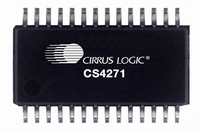
CS4271-CZZ Cirrus Logic Inc, CS4271-CZZ Datasheet - Page 30

CS4271-CZZ
Manufacturer Part Number
CS4271-CZZ
Description
IC CODEC AUD 24BIT 114DB 28TSSOP
Manufacturer
Cirrus Logic Inc
Type
Stereo Audior
Datasheet
1.CS4271-CZZ.pdf
(53 pages)
Specifications of CS4271-CZZ
Package / Case
28-TSSOP
Data Interface
Serial
Resolution (bits)
24 b
Number Of Adcs / Dacs
2 / 2
Sigma Delta
Yes
Dynamic Range, Adcs / Dacs (db) Typ
108 / 114
Voltage - Supply, Analog
4.75 V ~ 5.25 V
Voltage - Supply, Digital
3.1 V ~ 5.25 V
Operating Temperature
-10°C ~ 70°C
Mounting Type
Surface Mount
Number Of Adc Inputs
2
Number Of Dac Outputs
2
Conversion Rate
192 KSPS
Interface Type
Serial (I2C, I2S, SPI)
Resolution
24 bit
Operating Supply Voltage
3.3 V, 5 V
Maximum Operating Temperature
+ 70 C
Mounting Style
SMD/SMT
Minimum Operating Temperature
- 10 C
Number Of Channels
2 ADC/2 DAC
Thd Plus Noise
- 98 dB ADC / - 100 dB DAC
Lead Free Status / RoHS Status
Lead free / RoHS Compliant
For Use With
598-1003 - EVAL BOARD CS4271 STEREO CODEC
Lead Free Status / Rohs Status
Lead free / RoHS Compliant
Other names
598-1041-5
Available stocks
Company
Part Number
Manufacturer
Quantity
Price
Company:
Part Number:
CS4271-CZZ
Manufacturer:
Cirrus Logic Inc
Quantity:
1 843
Company:
Part Number:
CS4271-CZZ
Manufacturer:
SANKEN
Quantity:
34 562
Company:
Part Number:
CS4271-CZZR
Manufacturer:
HYNIX
Quantity:
1 420
5.2.4
In Control Port Mode, the CS4271 supports an internal digital loopback mode in which the output of the ADC is rout-
ed to the input of the DAC. This mode may be activated by setting the LOOP bit in the Mode Control 2 register (07h).
When this bit is set, the status of the DAC_DIF(2:0) bits in register 01h will be disregarded by the CS4271. Any
changes made to the DAC_DIF(2:0) bits while the LOOP bit is set will have no impact on operation until the LOOP
bit is released, at which time the Digital Interface Format of the DAC will operate according to the format selected in
the DAC_DIF(2:0) bits. While the LOOP bit is set, data will be present on the SDOUT pin in the format selected in
the ADC_DIF bit in register 06h.
5.2.5
The CS4271 may be configured to properly dither for 16-bit data. To do this, the Dither16 bit in the ADC Control
Register (06h) must be set. When set, a half bit of dither is added to the least significant bit of the 16 most significant
bits of the data word. The remaining bits should be disregarded. See Figure 10. This function is useful when 16-bit
devices are downstream of the ADC. This bit should not be set when using word lengths greater than 16 bits.
It should be noted that this function is supported for all serial audio output formats, and may be activated in either
Master or Slave Mode.
5.2.6
The Auto-Mute function is controlled by the status of the AMUTE bit in the DAC Control register. When set, the DAC
output will mute following the reception of 8192 consecutive audio samples of static 0 or -1. A single sample of non-
static data will release the mute. Detection and muting are done independently for each channel. Auto-Mute detec-
tion and muting can become dependent on either channel if the MUTECA=B function is enabled. The common mode
on the output will be retained and the Mute Control pin for that channel will become active during the mute period.
The muting function is effected, similar to volume control changes, by the Soft and ZeroCross bits in the DAC Vol-
ume and Mixing Control register. The AMUTE bit is set by default.
5.2.7
The operational amplifiers in the input circuitry driving the CS4271 may generate a small DC offset into the A/D con-
verter. The CS4271 includes a high pass filter after the decimator to remove any DC offset which could result in
recording a DC level, possibly yielding "clicks" when switching between devices in a multichannel system.
The high pass filter continuously subtracts a measure of the DC offset from the output of the decimation filter. The
high pass filter can be independently enabled and disabled for channels A and B. If the HPFDisableA or HPFDis-
ableB bit is set during normal operation, the current value of the DC offset for the corresponding channel is frozen
and this DC offset will continue to be subtracted from the conversion result. This feature makes it possible to perform
a system DC offset calibration by:
1) Running the CS4271 with the high pass filter enabled until the filter settles. See the Digital Filter Characteristics
2) Disabling the high pass filter and freezing the stored DC offset.
30
for filter settling time.
23
Internal Digital Loopback
Dither for 16-Bit Data
Auto-Mute
High Pass Filter and DC Offset Calibration
22
21
Figure 10. Example of Dither for 16-Bit Data with 24-Bit Left Justified Format
20
19
18
17
16-Bit W ord
16
15
14
13
12
11
10
½ Bit Dither
9
8
7
6
Disregard Contents
5
4
3
2
1
CS4271
0
DS592F1


