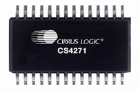
CS4271-CZZ Cirrus Logic Inc, CS4271-CZZ Datasheet - Page 38

CS4271-CZZ
Manufacturer Part Number
CS4271-CZZ
Description
IC CODEC AUD 24BIT 114DB 28TSSOP
Manufacturer
Cirrus Logic Inc
Type
Stereo Audior
Datasheet
1.CS4271-CZZ.pdf
(53 pages)
Specifications of CS4271-CZZ
Package / Case
28-TSSOP
Data Interface
Serial
Resolution (bits)
24 b
Number Of Adcs / Dacs
2 / 2
Sigma Delta
Yes
Dynamic Range, Adcs / Dacs (db) Typ
108 / 114
Voltage - Supply, Analog
4.75 V ~ 5.25 V
Voltage - Supply, Digital
3.1 V ~ 5.25 V
Operating Temperature
-10°C ~ 70°C
Mounting Type
Surface Mount
Number Of Adc Inputs
2
Number Of Dac Outputs
2
Conversion Rate
192 KSPS
Interface Type
Serial (I2C, I2S, SPI)
Resolution
24 bit
Operating Supply Voltage
3.3 V, 5 V
Maximum Operating Temperature
+ 70 C
Mounting Style
SMD/SMT
Minimum Operating Temperature
- 10 C
Number Of Channels
2 ADC/2 DAC
Thd Plus Noise
- 98 dB ADC / - 100 dB DAC
Lead Free Status / RoHS Status
Lead free / RoHS Compliant
For Use With
598-1003 - EVAL BOARD CS4271 STEREO CODEC
Lead Free Status / Rohs Status
Lead free / RoHS Compliant
Other names
598-1041-5
Available stocks
Company
Part Number
Manufacturer
Quantity
Price
Company:
Part Number:
CS4271-CZZ
Manufacturer:
Cirrus Logic Inc
Quantity:
1 843
Company:
Part Number:
CS4271-CZZ
Manufacturer:
SANKEN
Quantity:
34 562
Company:
Part Number:
CS4271-CZZR
Manufacturer:
HYNIX
Quantity:
1 420
8.
** All registers are read/write in I²C mode and write only in SPI mode, unless otherwise noted**
8.1
8.1.1
8.1.2
8.1.3
8.1.4
38
DAC_DIF2 DAC_DIF1 DAC_DIF0
M1
REGISTER DESCRIPTION
7
0
0
0
0
1
1
1
1
Mode Control 1 - Address 01h
Function:
Function:
Function:
Function:
Functional Mode (Bits 7:6)
Ratio Select (Bits 5:4)
Master / Slave Mode (Bit 3)
DAC Digital Interface Format (Bits 2:0)
Selects the required range of input sample rates.
These bits are used to select the clocking ratios in Control Port Mode. Please refer to Table 8, “Clock
Ratios - Control Port Mode With External Crystal,” on page 28 or Table 9, “Clock Ratios - Control Port
Mode Without External Crystal,” on page 29 for information on which of these bits to set to obtain spe-
cific clock ratios.
This bit selects either master or slave operation. Setting this bit will select master mode, while clearing
this bit will select slave mode.
The required relationship between LRCK, SCLK and SDIN for the DAC is defined by the DAC Digital
Interface Format and the options are detailed in Table 12 and Figures 3-5.
M1
0
0
1
1
M0
0
0
1
1
0
0
1
1
6
M0
0
1
0
1
Ratio1
0
1
0
1
0
1
0
1
5
Table 12. DAC Digital Interface Formats
Table 11. Functional Mode Selection
Single-Speed Mode: 4 to 50 kHz sample rates (default)
Single-Speed Mode: 4 to 50 kHz sample rates
Double-Speed Mode: 50 to 100 kHz sample rates
Quad-Speed Mode: 100 to 200 kHz sample rates
Left Justified, up to 24-bit data (default)
Ratio0
Right Justified, 16-bit Data
Right Justified, 24-bit Data
Right Justified, 20-bit Data
Right Justified, 18-bit Data
4
I
2
S, up to 24-bit data
Description
Reserved
Reserved
M/S
3
Mode
DAC_DIF2
2
Format
DAC_DIF1
0
1
2
3
4
5
1
CS4271
DAC_DIF0
Figure
DS592F1
3
4
5
5
5
5
0


