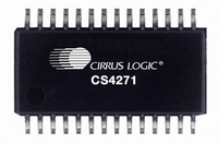
CS4271-CZZ Cirrus Logic Inc, CS4271-CZZ Datasheet - Page 8

CS4271-CZZ
Manufacturer Part Number
CS4271-CZZ
Description
IC CODEC AUD 24BIT 114DB 28TSSOP
Manufacturer
Cirrus Logic Inc
Type
Stereo Audior
Datasheet
1.CS4271-CZZ.pdf
(53 pages)
Specifications of CS4271-CZZ
Package / Case
28-TSSOP
Data Interface
Serial
Resolution (bits)
24 b
Number Of Adcs / Dacs
2 / 2
Sigma Delta
Yes
Dynamic Range, Adcs / Dacs (db) Typ
108 / 114
Voltage - Supply, Analog
4.75 V ~ 5.25 V
Voltage - Supply, Digital
3.1 V ~ 5.25 V
Operating Temperature
-10°C ~ 70°C
Mounting Type
Surface Mount
Number Of Adc Inputs
2
Number Of Dac Outputs
2
Conversion Rate
192 KSPS
Interface Type
Serial (I2C, I2S, SPI)
Resolution
24 bit
Operating Supply Voltage
3.3 V, 5 V
Maximum Operating Temperature
+ 70 C
Mounting Style
SMD/SMT
Minimum Operating Temperature
- 10 C
Number Of Channels
2 ADC/2 DAC
Thd Plus Noise
- 98 dB ADC / - 100 dB DAC
Lead Free Status / RoHS Status
Lead free / RoHS Compliant
For Use With
598-1003 - EVAL BOARD CS4271 STEREO CODEC
Lead Free Status / Rohs Status
Lead free / RoHS Compliant
Other names
598-1041-5
Available stocks
Company
Part Number
Manufacturer
Quantity
Price
Company:
Part Number:
CS4271-CZZ
Manufacturer:
Cirrus Logic Inc
Quantity:
1 843
Company:
Part Number:
CS4271-CZZ
Manufacturer:
SANKEN
Quantity:
34 562
Company:
Part Number:
CS4271-CZZR
Manufacturer:
HYNIX
Quantity:
1 420
8
Pin Name
XTO
XTI
MCLK
LRCK
SCLK
SDOUT
(M/S)
SDIN
DGND
VD
VL
M0
M1
I2S/LJ
RST
VQ1
VQ2
AINA
AINB
VQ3
VA
AGND
FILT+
AMUTEC
AOUTA-
AOUTA+
AOUTB+
AOUTB-
BMUTEC
1,2
17,
24,
25,
26,
10
12
13
14
15
16
18
19
20
21
22
23
27
28
11
#
3
4
5
6
7
8
9
Pin Description
Crystal Connections (Input/Output) - I/O pins for an external crystal which may be used to generate the
master clock. See “Crystal Applications (XTI/XTO)” on page 24 or “Crystal Applications (XTI/XTO)” on
page 27.
Master Clock (Input/Output) -Clock source for the delta-sigma modulators. See “Crystal Applications
(XTI/XTO)” on page 24 or “Crystal Applications (XTI/XTO)” on page 27.
Left Right Clock (Input/Output) - Determines which channel, Left or Right, is currently active on the
serial audio data line.
Serial Clock (Input/Output) - Serial clock for the serial audio interface.
Serial Audio Data Output (Output) - Output for two’s complement serial audio data. This pin must be
pulled-up or pulled-down to select Master or Slave Mode. See “Master/Slave Mode” on page 24.
Serial Audio Data Input (Input) - Input for two’s complement serial audio data.
Digital Ground (Input) - Ground reference for the internal digital section.
Digital Power (Input) - Positive power for the internal digital section.
Logic Power (Input) - Positive power for the digital input/output interface.
Mode Select 0 (Input) - In conjunction with M1, selects operating mode. Functionality is described in the
Hardware Mode Speed Configuration table.
Mode Select 1 (Input) - In conjunction with M0, selects operating mode. Functionality is described in the
Hardware Mode Speed Configuration table.
Serial Audio Interface Select (Input) - Selects either the left-justified or I
Interface.
Reset (Input) - The device enters a low power mode when this pin is driven low.
Quiescent Voltage (Output) - Filter connection for internal quiescent reference voltage.
Quiescent Voltage (Input) - Connection for internal quiescent reference voltage.
Analog Input (Input) - The full scale input level is specified in the ADC Analog Characteristics specifica-
tion table.
Quiescent Voltage (Input) - Connection for internal quiescent reference voltage.
Analog Power (Input) - Positive power for the internal analog section.
Analog Ground (Input) - Ground reference for the internal analog section.
Positive Voltage Reference (Output) - Positive reference voltage for the internal sampling circuits.
Channel A Mute Control (Output) - This pin is active during power-up initialization, reset, muting, when
master clock to left/right clock frequency ratio is incorrect, or power-down.
Differential Analog Audio Output (Output) - The full scale differential output level is specified in the
Analog Characteristics specification table.
Channel B Mute Control (Output) - This pin is active during power-up initialization, reset, muting, when
master clock to left/right clock frequency ratio is incorrect, or power-down.
2
S format for the Serial Audio
CS4271
DS592F1


