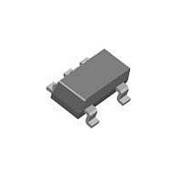
ILC7071AIM525X Fairchild Semiconductor, ILC7071AIM525X Datasheet - Page 9

ILC7071AIM525X
Manufacturer Part Number
ILC7071AIM525X
Description
Low Dropout (LDO) Regulators 0.10A LDO
Manufacturer
Fairchild Semiconductor
Datasheet
1.ILC7071AIM533X.pdf
(11 pages)
Specifications of ILC7071AIM525X
Number Of Outputs
1
Polarity
Positive
Input Voltage Max
0.6 V
Output Voltage
2.5 V
Output Type
Fixed
Dropout Voltage (max)
320 V
Output Current
0.15 A
Line Regulation
0.075 % / V
Load Regulation
0.25 %
Voltage Regulation Accuracy
1 %
Maximum Power Dissipation
150 mW
Maximum Operating Temperature
+ 85 C
Mounting Style
SMD/SMT
Package / Case
SOT-23
Minimum Operating Temperature
- 40 C
Lead Free Status / Rohs Status
Lead free / RoHS Compliant
PRODUCT SPECIFICATION
General PCB Layout Considerations
To achieve the full performance of the device, careful circuit
layout and grounding technique must be observed. Establish-
ing a small local ground, to which the GND pin, the output
and bypass capacitors are connected, is recommended, while
the input capacitor should be grounded to the main ground
plane.
The quiet local ground is then routed back to the main
ground plane using feedthrough vias.
In general, the high frequency compensation components
(input, bypass, and output capacitors) should be located as
close to the device as possible.
REV. 1.0.2 7/16/03
The proximity of the output capacitor is especially important
to achieve optimal noise compensation from the onboard
error amplifier, especially during high load conditions.
A large copper area in the local ground will provide the heat
sinking discussed above when high power dissipation signif-
icantly increases the temperature of the device.
Component-side copper provides significantly better thermal
performance for this surface-mount device, compared to that
obtained when using only copper planes on the underside.
ILC7071
9


