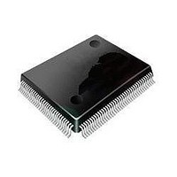
ST92F120V1Q7 STMicroelectronics, ST92F120V1Q7 Datasheet - Page 171

ST92F120V1Q7
Manufacturer Part Number
ST92F120V1Q7
Description
Microcontrollers (MCU) Flash 128K SPI/I2C
Manufacturer
STMicroelectronics
Datasheet
1.ST92F120V9Q7.pdf
(325 pages)
Specifications of ST92F120V1Q7
Data Bus Width
8 bit, 16 bit
Program Memory Type
Flash
Program Memory Size
128 KB
Data Ram Size
4 KB
Interface Type
I2C, SPI
Maximum Clock Frequency
24 MHz
Number Of Programmable I/os
77
Number Of Timers
5
Maximum Operating Temperature
+ 105 C
Mounting Style
SMD/SMT
Package / Case
PQFP-100
Minimum Operating Temperature
- 40 C
On-chip Adc
8 bit, 16 Channel
Lead Free Status / Rohs Status
No
Available stocks
Company
Part Number
Manufacturer
Quantity
Price
Company:
Part Number:
ST92F120V1Q7
Manufacturer:
ST
Quantity:
6 765
Part Number:
ST92F120V1Q7
Manufacturer:
ST
Quantity:
20 000
Part Number:
ST92F120V1Q7C
Manufacturer:
ST
Quantity:
20 000
Company:
Part Number:
ST92F120V1Q7DTR
Manufacturer:
MAXIM
Quantity:
2 854
- Current page: 171 of 325
- Download datasheet (3Mb)
MULTIFUNCTION TIMER (Cont’d)
TIMER MODE REGISTER (TMR)
R249 - Read/Write
Register Page: 10
Reset value: 0000 0000 (00h)
Bit 7 = OE1: Output 1 enable.
0: Disable the Output 1 (TxOUTB pin) and force it
1: Enable the Output 1 (TxOUTB pin)
Bit 6 = OE0: Output 0 enable.
0: Disable the Output 0 (TxOUTA pin) and force it
1: Enable the Output 0 (TxOUTA pin).
Bit 5 = BM: Bivalu e mode .
This bit works together with the RM1 and RM0 bits
to select the timer operating mode (see
0: Disable bivalue mode
1: Enable bivalue mode
Bit 4 = RM1: REG1R mode .
This bit works together with the BM and RM0 bits
to select the timer operating mode. Refer to
4.
Note: This bit has no effect when the Bivalue
Mode is enabled (BM=1).
OE1
high.
The relevant I/O bit must also be set to Alternate
Function
high
The relevant I/O bit must also be set to Alternate
Function
7
OE0
BM
RM1 RM0 ECK REN
Table
Table
C0
0
4).
Bit 3 = RM0: REG0R mode .
This bit works together with the BM and RM1 bits
to select the timer operating mode. Refer to
4.
Table 34. Timer Operating Modes
Bit 2 = ECK Timer clock control .
0: The prescaler clock source is selected depend-
1: Enter Parallel mode (for Timer 1 and Timer 3
Bit 1 = REN: Retrigger mode .
0: Enable retriggerable mode
1: Disable retriggerable mode
Bit 0 = CO: Continous/One shot mode .
0: Continuous mode (with autoreload on End of
1: One shot mode
BM RM1 RM0
1
1
0
0
0
0
ing on the IN0 - IN3 bits in the T_ICR register
only, no effect for Timer 0 and 2). See
0.1.2.12.
Count condition)
TMR Bits
x
0
1
0
1
x
0
1
0
0
1
1
MULTIFUNCTION TIMER (MFT)
Biload mode
Bicapture mode
Load from REG0R and Monitor on
REG1R
Load from REG0R and Capture on
REG1R
Capture on REG0R and Monitor on
REG1R
Capture on REG0R and REG1R
Timer Operating Modes
Section
171/324
Table
9
Related parts for ST92F120V1Q7
Image
Part Number
Description
Manufacturer
Datasheet
Request
R

Part Number:
Description:
8/16-bit Flash Mcu Family With Ram, Eeprom And J1850 Blpd
Manufacturer:
STMicroelectronics
Datasheet:

Part Number:
Description:
STMicroelectronics [RIPPLE-CARRY BINARY COUNTER/DIVIDERS]
Manufacturer:
STMicroelectronics
Datasheet:

Part Number:
Description:
STMicroelectronics [LIQUID-CRYSTAL DISPLAY DRIVERS]
Manufacturer:
STMicroelectronics
Datasheet:

Part Number:
Description:
BOARD EVAL FOR MEMS SENSORS
Manufacturer:
STMicroelectronics
Datasheet:

Part Number:
Description:
NPN TRANSISTOR POWER MODULE
Manufacturer:
STMicroelectronics
Datasheet:

Part Number:
Description:
TURBOSWITCH ULTRA-FAST HIGH VOLTAGE DIODE
Manufacturer:
STMicroelectronics
Datasheet:

Part Number:
Description:
Manufacturer:
STMicroelectronics
Datasheet:

Part Number:
Description:
DIODE / SCR MODULE
Manufacturer:
STMicroelectronics
Datasheet:

Part Number:
Description:
DIODE / SCR MODULE
Manufacturer:
STMicroelectronics
Datasheet:

Part Number:
Description:
Search -----> STE16N100
Manufacturer:
STMicroelectronics
Datasheet:

Part Number:
Description:
Search ---> STE53NA50
Manufacturer:
STMicroelectronics
Datasheet:

Part Number:
Description:
NPN Transistor Power Module
Manufacturer:
STMicroelectronics
Datasheet:


