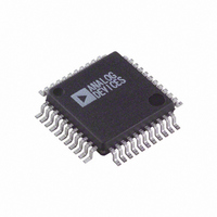
ADV7177KS-REEL Analog Devices Inc, ADV7177KS-REEL Datasheet - Page 17

ADV7177KS-REEL
Manufacturer Part Number
ADV7177KS-REEL
Description
IC DAC VIDEO NTSC 3-CH 44MQFP
Manufacturer
Analog Devices Inc
Type
Video Encoderr
Datasheet
1.ADV7177KSZ-REEL.pdf
(44 pages)
Specifications of ADV7177KS-REEL
Rohs Status
RoHS non-compliant
Applications
Set-Top Boxes, TV
Voltage - Supply, Analog
3 V ~ 3.6 V
Mounting Type
Surface Mount
Package / Case
44-MQFP, 44-PQFP
Adc/dac Resolution
9b
Screening Level
Commercial
Package Type
MQFP
Pin Count
44
Voltage - Supply, Digital
-
Lead Free Status / RoHS Status
Not Compliant
VIDEO TIMING DESCRIPTION
The ADV7177/ADV7178 are intended to interface to off-the-
shelf MPEG1 and MPEG2 decoders. Consequently, the
ADV7177/ADV7178 accept 4:2:2 YCrCb pixel data via a
CCIR-656 pixel port, and have several video timing modes
allowing them to be configured as either a system master
video timing generator or a slave to the system video timing
generator. The ADV7177/ADV7178 generate all of the required
horizontal and vertical timing periods and levels for the analog
video outputs. It is important to note that the CCIR-656 data
stream should not contain ancillary data packets as per the
BT1364 specification. This data can corrupt the internal
synchronization circuitry of the devices, resulting in loss of
synchronization on the output.
The ADV7177/ADV7178 calculate the width and placement of
analog sync pulses, blanking levels, and color burst envelopes.
Color bursts are disabled on appropriate lines, and serration
and equalization pulses are inserted where required.
In addition, the ADV7177/ADV7178 support a PAL or NTSC
square pixel operation in slave mode. The parts require an input
pixel clock of 24.5454 MHz for NTSC and an input pixel clock
Table 10. Luminance Internal Filter Specifications
Filter Selection
NTSC
PAL
NTSC
PAL
NTSC/PAL
NTSC
PAL
Table 11. Chrominance Internal Filter Specifications
Filter Selection
NTSC
PAL
MR04
0
0
0
0
1
1
1
Pass-Band
Cutoff (MHz)
1.0
1.3
MR03
0
0
1
1
0
1
1
Pass-Band
Ripple (dB)
0.085
0.04
Pass-Band
Cutoff (MHz)
2.3
3.4
1.0
1.4
4.0
2.3
3.4
Rev. C | Page 17 of 44
Stop-Band
Cutoff (MHz)
3.2
4.0
0.026
0.098
0.085
0.107
0.150
0.054
0.106
Pass-Band
Ripple (dB)
of 29.5 MHz for PAL. The internal horizontal line counters
place the various video waveform sections in the correct
location for the new clock frequencies.
The ADV7177/ADV7178 have four distinct master and four
distinct slave timing configurations. Timing control is
established with the bidirectional SYNC , BLANK , and
FIELD/ VSYNC pins. Timing Mode Register 1 can also be used
to vary the timing pulse widths and where they occur in
relation to each other.
Vertical Blanking Data Insertion (VBI)
It is possible to allow encoding of incoming YCbCr data on
those lines of VBI that do not bear line sync or pre- and post-
equalization pulses (see the Typical Performance Characteristics
section). This mode of operation is called partial blanking and
is selected by setting MR31 to 1. It allows the insertion of any
VBI data (opened VBI) into the encoded output waveform. This
data is present in the digitized incoming YCbCr data stream
(for example, WSS data, CGMS, and VPS). Alternatively, the
entire VBI can be blanked (no VBI data inserted) on these lines
by setting MR31 to 0.
Stop-Band
Attenuation (dB)
>40
>40
Stop-Band
Cutoff (MHz)
7.0
7.3
3.57
4.43
7.5
7.0
7.3
Attenuation
@ 1.3 MHz (dB)
0.3
0.02
Stop-Band
Attenuation (dB)
>54
>50
>27.6
>29.3
>40
>54
>50.3
ADV7177/ADV7178
F
4.2
5.0
2.1
2.7
5.35
4.2
5.0
F
2.05
2.45
3 dB
3 dB


