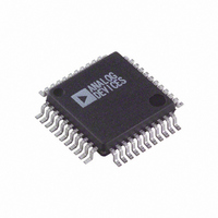
ADV7177KS-REEL Analog Devices Inc, ADV7177KS-REEL Datasheet - Page 31

ADV7177KS-REEL
Manufacturer Part Number
ADV7177KS-REEL
Description
IC DAC VIDEO NTSC 3-CH 44MQFP
Manufacturer
Analog Devices Inc
Type
Video Encoderr
Datasheet
1.ADV7177KSZ-REEL.pdf
(44 pages)
Specifications of ADV7177KS-REEL
Rohs Status
RoHS non-compliant
Applications
Set-Top Boxes, TV
Voltage - Supply, Analog
3 V ~ 3.6 V
Mounting Type
Surface Mount
Package / Case
44-MQFP, 44-PQFP
Adc/dac Resolution
9b
Screening Level
Commercial
Package Type
MQFP
Pin Count
44
Voltage - Supply, Digital
-
Lead Free Status / RoHS Status
Not Compliant
MR2 BIT DESCRIPTION
Square Pixel Control (MR20)
This bit is used to set up square pixel mode. This is available in
slave mode only. For NTSC, a 24.5454 MHz clock must be
supplied. For PAL, a 29.5 MHz clock must be supplied.
Active Video Line Duration (MR23)
This bit switches between two active video line durations. A 0
selects CCIR Rec. 601 (720 pixels PAL/NTSC) and a 1 selects
ITU-R.BT470 “analog” standard for active video duration
(710 pixels NTSC, 702 pixels PAL).
Chrominance Control (MR24)
This bit enables the color information to be switched on and off
the video output.
Burst Control (MR25)
This bit enables the burst information to be switched on and off
the video output.
RGB/YUV Control (MR26)
This bit enables the output from the RGB DACs to be set to
YUV output video standard. Bit MR06 of Mode Register 0 must
be set to Logic 1 before MR26 is set.
Table 12. DAC Output Configuration Matrix
MR06
0
0
1
1
In Table 12,
CVBS:
Y:
C:
U:
V:
R:
G:
B:
Low Power Control (MR27)
This bit enables the lower power mode of the ADV7177 and the
ADV7178. This reduces DAC current by 50%.
Composite video baseband signal
Green component video, for RGB mode
Luminance component signal, YUV or Y/C mode
Chrominance signal, for Y/C mode
Chrominance component signal, for YUV mode
Chrominance component signal, for YUV mode
Red component video, for RGB mode
Blue component video, for RGB mode
MR26
0
1
0
1
DAC A
CVBS
CVBS
B
U
DAC B
Y
Y
G
Y
DAC C
C
C
R
V
Rev. C | Page 31 of 44
NTSC PEDESTAL REGISTERS 3–0
PCE15–0, PCO15–0
(Subaddress [SR4–SR0] = 11–0EH)
These 8-bit-wide registers set up the NTSC pedestal on a line-
by-line basis in the vertical blanking interval for both odd and
even fields. Figure 40 show the four control registers. A Logic 1
in any of the bits of these registers has the effect of turning the
pedestal off on the equivalent line when used in NTSC.
MODE REGISTER 3 MR3 (MR37–MR30)
Address [SR4–SR0] = 12H
Mode Register 3 is an 8-bit-wide register. Figure 41shows the
various operations under the control of Mode Register 3.
MR3 BIT DESCRIPTION
Revision Code (MR30)
This bit is read only and indicates the revision of the device.
VBI_Pass-Through (MR31)
This bit determines whether or not data in the vertical blanking
interval (VBI) is output to the analog outputs or blanked. VBI
data insertion is not available in Slave Mode 0. Also, if BLANK
input control (TR03) is enabled, and VBI_Pass-Through is
enabled, TR03 has priority, that is, VBI data insertion does
not work.
Clock Output (MR33–MR32)
These bits control the synchronous clock output signal. The
clock can be 27 MHz, 13.5 MHz, or disabled, depending on the
values of these bit.
OSD Enable (MR35)
A Logic 1 in MR35 enables the OSD function on the ADV7177.
Input Default Color (MR36)
This bit determines the default output color from the DACs for
zero input data (or disconnected). A Logic 0 means that the
color corresponding to 00000000 is displayed. A Logic 1 forces
the output color to black for 00000000 input video data.
Reserved (MR37)
Zero should be written to this bit.
FIELD 1/3
FIELD 1/3
FIELD 2/4
FIELD 2/4
LINE 17 LINE 16 LINE 15 LINE 14 LINE 13 LINE 12 LINE 11 LINE 10
LINE 25 LINE 24 LINE 23 LINE 22 LINE 21 LINE 20 LINE 19 LINE 18
LINE 17 LINE 16 LINE 15 LINE 14 LINE 13 LINE 12 LINE 11 LINE 10
LINE 25 LINE 24 LINE 23 LINE 22 LINE 21 LINE 20 LINE 19 LINE 18
PCO15
PCE15
PCO7
PCE7
PCO14 PCO13
PCE14 PCE13
PCO6
PCE6
Figure 40. Pedestal Control Registers
PCO5
PCE5
PCO12
PCE12
PCO4
PCE4
PCO11
PCE11
PCO3
PCE3
ADV7177/ADV7178
PCO10
PCE10
PCO2
PCE2
PCO1
PCO9
PCE1
PCE9
PCO0
PCO8
PCE0
PCE8


