NC7WZ07L6X Fairchild Semiconductor, NC7WZ07L6X Datasheet - Page 5
NC7WZ07L6X
Manufacturer Part Number
NC7WZ07L6X
Description
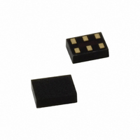
IC BUFF DL UHS O/DRAIN 6MICROPAK
Manufacturer
Fairchild Semiconductor
Series
7WZr
Datasheet
1.NC7WZ07P6X.pdf
(9 pages)
Specifications of NC7WZ07L6X
Logic Type
Buffer/Line Driver, Non-Inverting with Open Drain
Number Of Elements
2
Number Of Bits Per Element
2
Voltage - Supply
1.65 V ~ 5.5 V
Operating Temperature
-40°C ~ 85°C
Mounting Type
Surface Mount
Package / Case
6-MicroPak™
Logic Family
NC7WZ
Number Of Channels Per Chip
Dual
Polarity
Non-Inverting
Supply Voltage (max)
5.5 V
Supply Voltage (min)
1.65 V
Maximum Operating Temperature
85 C
Mounting Style
SMD/SMT
Input Bias Current (max)
1 uA
Low Level Output Current
32 mA
Maximum Power Dissipation
180 mW
Minimum Operating Temperature
- 40 C
Output Type
Open Drain
Number Of Lines (input / Output)
2 / 2
Propagation Delay Time
11.5 ns at 1.65 V, 9.5 ns at 1.8 V, 5.8 ns at 2.5 V, 4.4 ns at 3.3 V, 3.5 ns at 5 V
Lead Free Status / RoHS Status
Lead free / RoHS Compliant
Current - Output High, Low
-
Lead Free Status / Rohs Status
Lead free / RoHS Compliant
Available stocks
Company
Part Number
Manufacturer
Quantity
Price
Company:

Part Number:
NC7WZ07L6X
Manufacturer:
FAIRCHILD
Quantity:
15 000
Part Number:
NC7WZ07L6X
Manufacturer:
FAIRCHILD/仙童
Quantity:
20 000


© 2000 Fairchild Semiconductor Corporation
NC7WZ07 • Rev. 1.0.6
AC Electrical Characteristics
Note:
5.
Notes:
6.
7.
Note:
8.
9.
Symbol
t
PZL
C
C
C
OUT
, t
PD
IN
C
current consumption (I
operating current by the expression: I
Input PRR = 1.0MHz, t
Input=AC Waveform; t
PRR=Variable; Duty Cycle=50%.
C
PLZ
PD
L
includes load and stray capacitance.
is defined as the value of the internal equivalent capacitance which is derived from dynamic operating
Propagation Delay
Input Capacitance
Output Capacitance
Power Dissipation
Capacitance
Parameter
Figure 5. AC Test Circuit
(5)
r
CCD
W
=t
= 500ns.
f
=1.8ns.
) at no output loading and operating at 50% duty cycle. C
2.50 ± 0.20
3.30 ± 0.30
5.00 ± 0.50
2.50 ± 0.20
3.30 ± 0.30
5.00 ± 0.50
1.65
1.80
1.65
1.80
3.30
5.00
V
0
0
CC
CCD
C
RU=500
RD=500
V
C
RU=500
RD=500
V
Conditions
Figure 7. I
=(C
I
I
L
L
=2 x V
=2 x V
=50pF,
=50pF,
PD
)(V
CC
CC
CC
)(f
CCD
IN
5
)+(I
Test Circuit
Min.
1.8
1.8
1.2
0.8
0.5
1.8
1.8
1.2
0.8
0.5
CC
T
static).
A
=+25°C
Typ.
6.6
5.5
3.7
2.9
2.3
5.5
4.3
2.8
2.1
1.4
2.5
4.0
3
4
Figure 6. AC Waveforms
Max.
11.5
11.5
9.5
5.8
4.4
3.5
9.5
5.8
4.4
3.5
Min.
1.8
1.8
1.2
0.8
0.5
1.8
1.8
1.2
0.8
0.5
T
PD
A
+85°C
=-40 to
is related to I
Max.
12.6
10.5
12.6
10.5
6.4
4.8
3.9
6.4
4.8
3.9
Units Figure
pF
pF
CCD
ns
www.fairchildsemi.com
dynamic
Figure 5
Figure 6
Figure 7
Related parts for NC7WZ07L6X
Image
Part Number
Description
Manufacturer
Datasheet
Request
R

Part Number:
Description:
Fairchild Semiconductor [IGBT MODULE]
Manufacturer:
Fairchild Semiconductor
Datasheet:

Part Number:
Description:
Discrete Semiconductor Modules
Manufacturer:
Fairchild Semiconductor
Part Number:
Description:
Discrete Semiconductor Modules
Manufacturer:
Fairchild Semiconductor
Part Number:
Description:
This N-Channel MOSFET is produced using Fairchild Semiconductor’s advanced Power Trench® process
Manufacturer:
Fairchild Semiconductor
Datasheet:
Part Number:
Description:
This N-Channel MOSFET is produced using Fairchild Semiconductor’s advanced Power Trench® process
Manufacturer:
Fairchild Semiconductor
Datasheet:
Part Number:
Description:
This N-Channel MOSFET is produced using Fairchild Semiconductor’s advanced PowerTrench® process
Manufacturer:
Fairchild Semiconductor
Datasheet:
Part Number:
Description:
This N-Channel MOSFET is produced using Fairchild Semiconductor’s advanced PowerTrench® process
Manufacturer:
Fairchild Semiconductor
Datasheet:
Part Number:
Description:
This N-Channel MOSFET is produced using Fairchild Semiconductor’s advanced Power Trench® process
Manufacturer:
Fairchild Semiconductor
Datasheet:
Part Number:
Description:
This N-Channel logic Level MOSFETs are produced using Fairchild Semiconductor‘s advanced Power Trench® process that has been special tailored to minimize the on-state resistance and yet maintain superior switching performance
Manufacturer:
Fairchild Semiconductor
Datasheet:
Part Number:
Description:
This N-Channel MOSFET is produced using Fairchild Semiconductor’s advanced Power Trench® process
Manufacturer:
Fairchild Semiconductor
Datasheet:
Part Number:
Description:
This N-Channel SyncFET™ is produced using Fairchild Semiconductor’s advanced PowerTrench® process
Manufacturer:
Fairchild Semiconductor
Datasheet:
Part Number:
Description:
This N-Channel SyncFET™ is produced using Fairchild Semiconductor’s advanced PowerTrench® process
Manufacturer:
Fairchild Semiconductor
Datasheet:
Part Number:
Description:
This N-Channel SyncFET™ is produced using Fairchild Semiconductor’s advanced PowerTrench® process
Manufacturer:
Fairchild Semiconductor
Datasheet:
Part Number:
Description:
This N-Channel logic Level MOSFETs are produced using Fairchild Semiconductor‘s advanced Power Trench® process that has been special tailored to minimize the on-state resistance and yet maintain superior switching performance
Manufacturer:
Fairchild Semiconductor
Datasheet:
Part Number:
Description:
This N-Channel MOSFET is produced using Fairchild Semiconductor’s advanced Power Trench® process that has been especially tailored to minimize the on-state resistance and yet maintain superior switching performance
Manufacturer:
Fairchild Semiconductor
Datasheet: