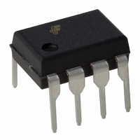
FSDM311 Fairchild Semiconductor, FSDM311 Datasheet

FSDM311
Specifications of FSDM311
FSDM311_NL
Available stocks
Related parts for FSDM311
FSDM311 Summary of contents
Page 1
... When compared to a discrete MOSFET and controller or RCC switching converter solution, the FSDM311 device reduces total component count and design size and weight; while increasing efficiency, productivity, and system reliability. This device provides a basic platform that is well suited for the design of cost- effective flyback converters ...
Page 2
... FSDM311 Rev. 1.1.0 • 7/14/06 Product FSDM311 FSDM311L Notes: 1. Maximum practical continuous power in open-frame design with sufficient drain pattern as a heat sink, at 50°C ambient. 2. 230VAC or 100/115VAC with doubler. Figure 2 Functional Block Diagram of FSDM311 2 OUTPUT POWER TABLE (1) Open Frame (2) 230VAC±15% 85~265VAC 13W 8W 13W 8W www ...
Page 3
... NC 5 Vstr 6,7,8 Drain © 2003 Fairchild Semiconductor Corporation FSDM311 Rev. 1.1.0 • 7/14/06 Figure 3 Pin Configuration (Top View) Pin Function Description Ground. SenseFET source terminal on primary side and internal control ground. Positive supply voltage input. Although connected to an auxiliary transformer winding, current is supplied from pin 5 (Vstr) via an internal switch during start-up (see Internal Block Diagram section) ...
Page 4
... Free standing with no heat sink, without copper clad. (Measurement Condition – Just before junction temperature T enters into OTP Measured on the DRAIN pin close to plastic interface. All items are tested with the standards JESD 51-2 and 51-10 (DIP). © 2003 Fairchild Semiconductor Corporation FSDM311 Rev. 1.1.0 • 7/14/06 Parameter (3) (4) Parameter (5) (6) 4 ...
Page 5
... Pulse test: Pulse width ≤ 300μs, duty ≤ 2%. 8. These parameters, although guaranteed, are tested in EDS (wafer test) process. 9. These parameters, although guaranteed, are not 100% tested in production. © 2003 Fairchild Semiconductor Corporation FSDM311 Rev. 1.1.0 • 7/14/06 Conditions V =650V ...
Page 6
... Figure 6. Start Threshold Voltage (V 1.15 1.10 1.05 1.00 0.95 0.90 0.85 - Temperature [°C] Figure 8. Operating Frequency (f © 2003 Fairchild Semiconductor Corporation FSDM311 Rev. 1.1.0 • 7/14/06 = 25°C. A 1.15 1.10 1.05 1.00 0.95 0.90 0.85 100 150 -50 ) vs. T Figure 5. Operating Supply Current (I ...
Page 7
... Figure 12. Shutdown Delay Current (I 1.15 1.10 1.05 1.00 0.95 0.90 0.85 - Temperature [°C] Figure 14. Over-Voltage Protection (V © 2003 Fairchild Semiconductor Corporation FSDM311 Rev. 1.1.0 • 7/14/06 (continued) 1.15 1.10 1.05 1.00 0.95 0.90 0.85 -50 100 150 ) vs. T Figure 11. Feedback Source Current (I ...
Page 8
... Start-up: At start-up, the internal high-voltage current source supplies the internal bias and charges the external Vcc capacitor, as shown in Figure 15. In the case of the FSDM311, when Vcc reaches 9V, the device starts switching and the internal high-voltage current source stops charging the capacitor. The device is in normal operation provided that Vcc does not drop below 7V ...
Page 9
... SenseFET turns on. LEB 4. Protection Circuit: The FSDM311 has several protective functions, such as overload protection (OLP), over-voltage protection (OVP), under-voltage lockout (UVLO), and thermal shutdown (TSD). Because these protection circuits are fully integrated in the IC without external components, the reliability is improved without increasing cost ...
Page 10
... Burst Operation: To minimize the power dissipation in standby mode, the FSDM311 enters burst--mode operation. As the load decreases, the feedback voltage decreases. The device automatically enters burst mode when the feedback voltage drops below V this point, switching stops and the output voltages start to drop ...
Page 11
... F capacitor (C ); and decrease a feedback gain resistor shown in Figure 24. F © 2003 Fairchild Semiconductor Corporation FSDM311 Rev. 1.1.0 • 7/14/06 the chattering or in the ambient a piezoelectric effect, Figure24. Typical Feedback Network of FPS ...
Page 12
... Input, 10W Output Schematic The selection of aux-winding diode D2 affects Aux-Output (Vcc) regulation. If another component should be used, its Note: validity must be verified experimentally. Figure 25. Schematic of FSDM311 PC Standby Power © 2003 Fairchild Semiconductor Corporation FSDM311 Rev. 1.1.0 • 7/14/06 Input Voltage 12.5W ...
Page 13
... Transformer Construction Figure 27. Winding Direction for Each Winding (Left) and Cross-Sectional View for W5v / Wcc Insulation Taping (Right) © 2003 Fairchild Semiconductor Corporation FSDM311 Rev. 1.1.0 • 7/14/06 Figure 26. Transformer Construction Diagram Insulation Tape Figure 28. Details on W5v / Wcc Insulation Taping 13 3~4mm ...
Page 14
... First Resonant Frequency Core & Bobbin Core: EE1927S (SAMWHA Electronics, PL7 / Ae = 23.4mm Bobbin: Vertical, 12 pins, 6 pins at each side, 20mm width (bobbin wall to wall) © 2003 Fairchild Semiconductor Corporation FSDM311 Rev. 1.1.0 • 7/14/06 Pin(S → F) Wire (φ:mm) Insulation: Polyester Tape t = 0.025mm, 2 Layers f → ...
Page 15
... ZD1 28 1 ZD2 (ZD3) (ZD4) © 2003 Fairchild Semiconductor Corporation FSDM311 Rev. 1.1.0 • 7/14/06 Value 1.5nF 50V MLCC X7R, ±10% Tolerance SMD 0805 1nF AC250V Y1 Safety Capacitor 10nF 1KV Ceramic 1nF 1KV Ceramic Low ESR (40mΩ) Electrolytic 1000µF 10V (e.g. Samwha Electric WB series) Low ESR (70mΩ ...
Page 16
... Layout Information Single layer, size 59 x 40mm Figure 30. PCB Layout – Top- Side Print (Top) and Bottom-Side Print (Bottom) © 2003 Fairchild Semiconductor Corporation FSDM311 Rev. 1.1.0 • 7/14/06 16 www.fairchildsemi.com ...
Page 17
... Physical Dimensions 8-DIP Dimensions are in millimeters (inches) unless otherwise noted. © 2003 Fairchild Semiconductor Corporation FSDM311 Rev. 1.1.0 • 7/14/06 17 www.fairchildsemi.com ...
Page 18
... Physical Dimensions (Continued) 8-LSOP Dimensions are in millimeters (inches) unless otherwise noted. © 2003 Fairchild Semiconductor Corporation FSDM311 Rev. 1.1.0 • 7/14/06 18 www.fairchildsemi.com ...
Page 19
... PRODUCT STATUS DEFINITIONS Definition of Terms Datasheet Identification Advance Information Preliminary No Identification Needed Obsolete © 2003 Fairchild Semiconductor Corporation FSDM311 Rev. 1.1.0 • 7/14/06 OCXPro™ ® OPTOLOGIC OPTOPLANAR™ PACMAN™ POP™ Power247™ PowerEdge™ ...


