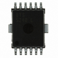
BTS5240L Infineon Technologies, BTS5240L Datasheet - Page 7

BTS5240L
Manufacturer Part Number
BTS5240L
Description
IC SWITCH PWR HISIDE DSO-12
Manufacturer
Infineon Technologies
Type
High Sider
Datasheet
1.BTS5240L.pdf
(17 pages)
Specifications of BTS5240L
Input Type
Non-Inverting
Number Of Outputs
2
On-state Resistance
21 mOhm
Current - Output / Channel
6A
Current - Peak Output
11A
Voltage - Supply
4.5 V ~ 28 V
Operating Temperature
-40°C ~ 150°C
Mounting Type
Surface Mount
Package / Case
DSO-12
Lead Free Status / RoHS Status
Contains lead / RoHS non-compliant
Other names
BTS5240L
BTS5240LINTR
BTS5240LNT
BTS5240LT
SP000014002
BTS5240LINTR
BTS5240LNT
BTS5240LT
SP000014002
Available stocks
Company
Part Number
Manufacturer
Quantity
Price
Company:
Part Number:
BTS5240L
Manufacturer:
INFINEON
Quantity:
3 333
Company:
Part Number:
BTS5240L
Manufacturer:
INFINEON
Quantity:
23 805
Part Number:
BTS5240L
Manufacturer:
INFINEON/英飞凌
Quantity:
20 000
Electrical Characteristics
Parameter and Conditions,
at T
Operating Parameters
Off-State output current (included in
V
Operating current
V
Protection Functions
Current limit,
Current limit adjustment threshold voltage
Repetitive short circuit current limit
T
High level
Low level
Initial short circuit shutdown time
T
Output clamp (inductive load switch off)
I
Thermal overload trip temperature
Thermal hysteresis
1 Add I
2 Integrated protection functions are designed to prevent IC destruction under fault conditions
described in the data sheet. Fault conditions are considered as "outside" normal operating range.
Protection functions are not designed for continuous repetitive operation .
3 At the beginning of the short circuit the double current is possible for a short time.
4 If channels are connected in parallel, output clamp is usually accomplished by the
channel with the lowest V Out(CL) .
L
j
j,start
IN
IN
= 40 mA
= T
j
= -40...+150 °C, V
= 0 V, each channel
= 5 V, per active channel
IS , if I IS > 0
jt (see timing diagrams on page 15)
= 25°C ; V
Low level;
High level;
( see timing diagrams, page 15 )
bb
1)
bb
= 13,5 V
if potential at CLA = high
= 9...16 V,
if potential at CLA = low
2)
two active channels
two active channels
each of the two channels
unless otherwise specified
one active channel:
one active channel:
I
bb(off)
4)
high level:
low level:
)
Page 7
3)
3)
:
:
Symbol
I
I
I
V
V
I
t
V
T
L(off)
GND
L(LIM)
L(SCr)
off(SC)
T
CLA(T-)
CLA(T+)
Out(CL)
jt
jt
min.
150
2.0
40
-
-
7
-
-
-
-
-
-
-
-
-
Values
typ.
170
1.5
1.6
0.8
-15
11
50
40
40
10
4
7
7
-
-
BTS 5240L
2005-06-03
max.
4.0
14
60
8
4
-
-
-
-
-
-
-
-
-
-
Unit
µA
mA
A
V
A
ms
V
°C
K


