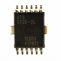
BTS5235-2L Infineon Technologies, BTS5235-2L Datasheet - Page 19

BTS5235-2L
Manufacturer Part Number
BTS5235-2L
Description
IC PWR SWITCH HISIDE PG-DSO-12-9
Manufacturer
Infineon Technologies
Series
PROFET®r
Type
High Sider
Datasheet
1.BTS5235-2L.pdf
(25 pages)
Specifications of BTS5235-2L
Package / Case
DSO-12
Input Type
Non-Inverting
Number Of Outputs
2
On-state Resistance
45 mOhm
Current - Output / Channel
3.5A
Current - Peak Output
28A
Voltage - Supply
4.5 V ~ 28 V
Operating Temperature
-40°C ~ 150°C
Mounting Type
Surface Mount
On Resistance (max)
0.045 Ohms
Maximum Operating Temperature
+ 150 C
Minimum Operating Temperature
- 40 C
Maximum Power Dissipation
1600 mW
Mounting Style
SMD/SMT
Supply Current
3.6 mA
Lead Free Status / RoHS Status
Lead free / RoHS Compliant
Lead Free Status / RoHS Status
Lead free / RoHS Compliant, Lead free / RoHS Compliant
Other names
BTS5235-2LINTR
BTS52352LXT
SP000280715
BTS52352LXT
SP000280715
Available stocks
Company
Part Number
Manufacturer
Quantity
Price
Part Number:
BTS5235-2L
Manufacturer:
INFINEON/英飞凌
Quantity:
20 000
7.1
The standard diagnosis signal is a current sense signal proportional to the load current. The accuracy of the ratio
( k
connected to the current sense pin. It is recommended to use sense resistors R
Figure 14
Details about timings between the diagnosis signal I
can be found in
Figure 15
In case of over-load as well as over-temperature, the voltage V
according input pin is high. This means, even if the overload disappears after the first thermal shutdown or when
the device keeps switching on and off in over-load condition (thermal toggling), the diagnosis signal ( V
constantly available. Please refer to
first thermal shutdown, the diagnosis signal (
of the overload.
1) The curves show the behavior based on characterization data. The marked points are guaranteed in this Data Sheet in
Data Sheet
ILIS
Section 7.4
=
I
L
/
I
IS
) depends on the temperature. Please refer to following
ON-State Diagnosis
Current sense ratio k
Timing of Diagnosis Signal in ON-state
(Position 7.4.6).
Figure
V
OUT
IN
I
I
IS
L
OFF
8000
7000
6000
5000
4000
3000
2000
1000
15.
ON
0
t
ON
t
sIS(ON)
0.5
ILIS
Figure 16
1)
1
V
IS(fault)
for details. Please note, that if the overload disappears before the
1.5
) may remain for approximately 300 s longer than the duration
IS
and the output voltage V
19
t
sIS(LC)
2
normal operation over load (current limitation)
I
L
/A
IS(fault)
2.5
Figure 14
is fed to the diagnosis pins as long as the
t
sIS(OVL)
Smart High-Side Power Switch
3
IS
T
T
OUT
j
for details. Usually a resistor R
j
V
= 150 C
> 500
= -40 C
dummy
dummy
IS(fault)
3.5
and load current I
/ R
S
SwitchOn .emf
A typical value is 4.7 k .
4
t
t
t
t
Rev.1.1, 2008-09-01
BTS5235-2L
L
in ON-state
Diagnosis
IS(fault)
IS
) is
is


