FAN5308MPX Fairchild Semiconductor, FAN5308MPX Datasheet
FAN5308MPX
Specifications of FAN5308MPX
Available stocks


Related parts for FAN5308MPX


FAN5308MPX Summary of contents
Page 1
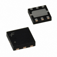
... The FAN5308 is available in a 3x3mm 6-lead MLP package. Package Type Adjustable 3x3mm 6-Lead MLP 3.3μH PGND 5KΩ R1 (AGND 10KΩ Figure 1. Typical Application June 2007 Order Code FAN5308MPX V OUT 1.2V (800mA) C OUT 2 x 10μF www.fairchildsemi.com tm ...
Page 2
... Do not float this pin Feedback Input. Adjustable voltage option, connect this pin to the resistor divider Connection Pin Switching Node. This pin is connected to the internal MOSFET switches. © 2005 Fairchild Semiconductor Corporation FAN5308 Rev. 1.0 PGND 2 5 ...
Page 3
... Inductor (3) Input Capacitor (3) Output Capacitor Operating Ambient Temperature Range Operating Junction Temperature Range Note: 3. Refer to the Applications section for details. © 2005 Fairchild Semiconductor Corporation FAN5308 Rev. 1.0.2 Parameter (1) ), 3x3mm 6-lead MLP JC ( strong function of PCB material, board thickness, thickness and JA 3 Min. ...
Page 4
... ST Notes: 4. Refer to the Application section for details. 5. For output voltages ≤ 1.2V, a 40µF output capacitor value is required to achieve a maximum output accuracy of 3% while operating in power-save mode (PFM mode). © 2005 Fairchild Semiconductor Corporation FAN5308 Rev. 1.0.2 = 350mA, V =1.2V OUT OUT = 25° ...
Page 5
... Load Current (mA) Figure 5. Efficiency vs. Load Current OUT 10kΩ 2.5 3.0 3.5 4.0 Input Voltage (V) Figure 7. Quiescent Current vs. Input Voltage © 2005 Fairchild Semiconductor Corporation FAN5308 Rev. 1.0.2 = 10kΩ, unless otherwise noted. 2 100 3. 1.2V OUT 100 1000 0.1 1.214 1 ...
Page 6
... A IN OUT Time (1μs/div) Figure 9. PWM Mode 100mA V = 1.2V OUT Time (10μs/div) Figure 11. Load Transient Response Time (100μs/div) Figure 13. Start-Up Response © 2005 Fairchild Semiconductor Corporation FAN5308 Rev. 1.0.2 (Continued) = 10kΩ, unless otherwise noted. 2 600mA V = 1.2V OUT I = 10mA OUT 6 Time (5μ ...
Page 7
... After a minimum dead time, the N-channel transistor is turned on and the inductor current ramps down. As the clock cycle is completed, the N-channel switch is turned off and the next clock cycle starts. ©2005 Fairchild Semiconductor Corporation FAN5308 Rev. 1.0.2 EN UNDER-VOLTAGE IS ...
Page 8
... I = Output current LOAD R = Inductor DC resistance L ©2005 Fairchild Semiconductor Corporation FAN5308 Rev. 1.0.2 UVLO and Soft Start The reference and the circuit remain reset until the V crosses its UVLO threshold. The FAN5308 has an internal soft-start circuit that limits the inrush current during start-up. This prevents possible voltage drops of the input voltage and eliminates the out- put voltage overshoot ...
Page 9
... Vendor 3.3µH Panasonic 3.3µH Murata Table 1: Recommended Inductors ©2005 Fairchild Semiconductor Corporation FAN5308 Rev. 1.0.2 Capacitors Selection For best performances, a low-ESR input capacitor is required. A ceramic capacitor of at least 10µF, placed close to the V output capacitor determines the output ripple and the transient response ...
Page 10
... Mechanical Dimensions Dimensions are in millimeters unless otherwise noted. © 2005 Fairchild Semiconductor Corporation FAN5308 Rev. 1.0.2 Figure 18. 3x3mm 6-Lead MLP 10 www.fairchildsemi.com ...
Page 11
... Fairchild Semiconductor Corporation FAN5308 Rev. 1.0.2 11 www.fairchildsemi.com ...