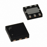
FAN5308MPX Fairchild Semiconductor, FAN5308MPX Datasheet - Page 8

FAN5308MPX
Manufacturer Part Number
FAN5308MPX
Description
IC CONV DC-DC 800MA HI 3X3 6MLP
Manufacturer
Fairchild Semiconductor
Type
Step-Down (Buck), PWM - Current Moder
Datasheet
1.FAN5308MPX.pdf
(11 pages)
Specifications of FAN5308MPX
Internal Switch(s)
Yes
Synchronous Rectifier
Yes
Number Of Outputs
1
Voltage - Output
0.8 ~ 5.5 V
Current - Output
800mA
Frequency - Switching
1.3kHz
Voltage - Input
2.5 V ~ 5.5 V
Operating Temperature
-40°C ~ 85°C
Mounting Type
*
Package / Case
6-MLP
Voltage - Supply
2.5 V ~ 5.5 V
Frequency-max
1.3MHz
Duty Cycle
100%
Pwm Type
Current Mode
Buck
Yes
Boost
No
Flyback
No
Inverting
No
Doubler
No
Divider
No
Cuk
No
Isolated
No
Output Voltage
0.8 V
Mounting Style
SMD/SMT
Operating Temperature Range
- 40 C to + 85 C
Primary Input Voltage
5.5V
No. Of Outputs
1
Output Current
800mA
No. Of Pins
6
Peak Reflow Compatible (260 C)
Yes
Rohs Compliant
Yes
Leaded Process Compatible
Yes
Lead Free Status / RoHS Status
Lead free / RoHS Compliant
Available stocks
Company
Part Number
Manufacturer
Quantity
Price
Part Number:
FAN5308MPX
Manufacturer:
FAIRCHILD/仙童
Quantity:
20 000
©2005 Fairchild Semiconductor Corporation
FAN5308 Rev. 1.0.2
The N-channel transistor is turned off before the inductor
current becomes negative. At this time, the P-channel is
switched on again, starting the next pulse. The converter
continues these pulses until the high threshold (typical
1.6% above nominal value) is reached. A higher output
voltage in PFM mode gives additional headroom for the
voltage drop during a load transient from light to full load.
The voltage overshoot during this load transient is also
minimized due to active regulation during turn on of the
N-channel rectifier switch. The device stays in sleep
mode until the output voltage falls below the low thresh-
old. The FAN5308 enters the PWM mode as soon as the
output voltage can no longer be regulated in PFM with
constant peak current.
100% Duty Cycle Operation
As the input voltage approaches the output voltage and
the duty cycle exceeds the typical 95%, the converter
turns the P-channel transistor continuously on. In this
mode, the output voltage is equal to the input voltage,
minus the voltage drop across the P-channel transistor:
where:
R
I
R
V
LOAD
dsON
L
OUT
= Inductor DC resistance
= Output current
= V
= P-channel switch on resistance
IN
– I
LOAD
(R
dsON
+ R
L
)
EQ. 2
8
UVLO and Soft Start
The reference and the circuit remain reset until the V
crosses its UVLO threshold.
The FAN5308 has an internal soft-start circuit that limits
the inrush current during start-up. This prevents possible
voltage drops of the input voltage and eliminates the out-
put voltage overshoot. The soft-start is implemented as a
digital circuit, increasing the switch current in four steps
to the P-channel current limit (1500mA). Typical start-up
time for a 20µF output capacitor and a load current of
800mA is 800µs.
Short-Circuit Protection
The switch peak current is limited cycle-by-cycle to a typ-
ical value of 1500mA. In the event of an output voltage
short circuit, the device operates with a frequency of
400kHz and minimum duty cycle; therefore, the average
input current is typically 200mA.
Thermal Shutdown
When the die temperature exceeds 150°C, a reset
occurs and remains in effect until the die cools to 130°C.
At that time, the circuit is allowed to restart.
www.fairchildsemi.com
IN


