PCM18XT0 Microchip Technology, PCM18XT0 Datasheet - Page 38
PCM18XT0
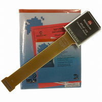
Manufacturer Part Number
PCM18XT0
Description
MODULE PROC PIC18F4685
Manufacturer
Microchip Technology
Datasheet
1.PCM18XT0.pdf
(484 pages)
Specifications of PCM18XT0
Accessory Type
Processor Module
Product
Microcontroller Modules
Core Processor
PIC18F4685
Lead Free Status / RoHS Status
Not applicable / Not applicable
For Use With/related Products
ICE2000
For Use With
ICE2000 - EMULATOR MPLAB-ICE 2000 POD
Lead Free Status / RoHS Status
Lead free / RoHS Compliant, Not applicable / Not applicable


PIC18F2682/2685/4682/4685
If the IRCF bits were previously at a non-zero value or
if INTSRC was set before setting SCS1 and the
INTOSC source was already stable, the IOFS bit will
remain set.
On transitions from RC_RUN mode to PRI_RUN mode,
the device continues to be clocked from the INTOSC
multiplexer while the primary clock is started. When the
FIGURE 3-3:
FIGURE 3-4:
DS39761C-page 38
INTRC
OSC1
CPU
Clock
Peripheral
Clock
Program
Counter
Note 1: T
CPU Clock
Multiplexer
PLL Clock
Peripheral
INTOSC
Program
Counter
Output
OSC1
Clock
Q1
SCS1:SCS0 bits Changed
OST
Q2
TRANSITION TIMING TO RC_RUN MODE
PC
TRANSITION TIMING FROM RC_RUN MODE TO PRI_RUN MODE
= 1024 T
Q3
Q4
OSC
Q1
; T
Q1
PLL
1
T
OST (1)
= 2 ms (approx). These intervals are not shown to scale.
PC
2
Q2
Clock Transition
3
T
PLL
OSTS bit Set
Q3
(1)
PC + 2
n-1
Q4
primary clock becomes ready, a clock switch to the
primary clock occurs (see Figure 3-4). When the clock
switch is complete, the IOFS bit is cleared, the OSTS
bit is set and the primary clock is providing the device
clock. The IDLEN and SCS bits are not affected by the
switch. The INTRC source will continue to run if either
the WDT or the Fail-Safe Clock Monitor is enabled.
n
Q1
1
Transition
2
Clock
n-1 n
Q2
PC + 2
Q3
Q2
Q4
© 2009 Microchip Technology Inc.
Q3 Q4
Q1
Q1
Q2
PC + 4
PC + 4
Q2
Q3
Q3
Related parts for PCM18XT0
Image
Part Number
Description
Manufacturer
Datasheet
Request
R

Part Number:
Description:
Manufacturer:
Microchip Technology Inc.
Datasheet:
Part Number:
Description:
Manufacturer:
Microchip Technology Inc.
Datasheet:
Part Number:
Description:
Manufacturer:
Microchip Technology Inc.
Datasheet:
Part Number:
Description:
Manufacturer:
Microchip Technology Inc.
Datasheet:
Part Number:
Description:
Manufacturer:
Microchip Technology Inc.
Datasheet:
Part Number:
Description:
Manufacturer:
Microchip Technology Inc.
Datasheet:
Part Number:
Description:
Manufacturer:
Microchip Technology Inc.
Datasheet:
Part Number:
Description:
Manufacturer:
Microchip Technology Inc.
Datasheet: