DTMFDECODER-RD Silicon Laboratories Inc, DTMFDECODER-RD Datasheet - Page 119
DTMFDECODER-RD
Manufacturer Part Number
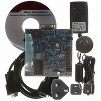
DTMFDECODER-RD
Description
KIT REF DESIGN DTMF DECODER
Manufacturer
Silicon Laboratories Inc
Specifications of DTMFDECODER-RD
Mfg Application Notes
DTMF Decoder Ref Design AppNote
Main Purpose
Telecom, DTMF Decoder
Embedded
No
Utilized Ic / Part
C8051F300
Primary Attributes
8kHz Sampling Rate ADC
Secondary Attributes
16 Goertzel Filters
Processor To Be Evaluated
C8051F300
Interface Type
RS-232
Lead Free Status / RoHS Status
Contains lead / RoHS non-compliant
Lead Free Status / RoHS Status
Lead free / RoHS Compliant, Contains lead / RoHS non-compliant
Other names
336-1283


C8051F300/1/2/3/4/5
13.4.2. SMB0CN Control Register
SMB0CN is used to control the interface and to provide status information (see SFR Definition 13.2). The
higher four bits of SMB0CN (MASTER, TXMODE, STA, and STO) form a status vector that can be used to
jump to service routines. MASTER and TXMODE indicate the master/slave state and transmit/receive
modes, respectively.
The STA bit indicates that a START has been detected or generated since the last SMBus interrupt. When
set to ‘1’, the STA bit will cause the SMBus to enter Master mode and generate a START when the bus
becomes free. STA is not cleared by hardware after the START is generated; it must be cleared by soft-
ware.
As a master, writing the STO bit will cause the hardware to generate a STOP condition and end the current
transfer after the next ACK cycle. STO is cleared by hardware after the STOP condition is generated. As a
slave, STO indicates that a STOP condition has been detected since the last SMBus interrupt. STO is also
used in slave mode to manage the transition from slave receiver to slave transmitter; see
Section 13.5.4
for details on this procedure.
If STO and STA are both set to ‘1’ (while in Master Mode), a STOP followed by a START will be generated.
As a receiver, writing the ACK bit defines the outgoing ACK value; as a transmitter, reading the ACK bit
indicates the value received on the last ACK cycle. ACKRQ is set each time a byte is received, indicating
that an outgoing ACK value is needed. When ACKRQ is set, software should write the desired outgoing
value to the ACK bit before clearing SI. A NACK will be generated if software does not write the ACK bit
before clearing SI. SDA will reflect the defined ACK value immediately following a write to the ACK bit;
however SCL will remain low until SI is cleared. If a received slave address is not acknowledged, further
slave events will be ignored until the next START is detected.
The ARBLOST bit indicates that the interface has lost an arbitration. This may occur anytime the interface
is transmitting (master or slave). A lost arbitration while operating as a slave indicates a bus error condi-
tion. ARBLOST is cleared by hardware each time SI is cleared.
The SI bit (SMBus Interrupt Flag) is set at the beginning and end of each transfer, after each byte frame, or
when an arbitration is lost; see Table 13.3 for more details.
Important Note About the SI Bit: The SMBus interface is stalled while SI is set; thus SCL is held low, and
the bus is stalled until software clears SI.
Table 13.3 lists all sources for hardware changes to the SMB0CN bits. Refer to Table 13.4 for SMBus sta-
tus decoding using the SMB0CN register.
Rev. 2.9
119
Related parts for DTMFDECODER-RD
Image
Part Number
Description
Manufacturer
Datasheet
Request
R

Part Number:
Description:
SMD/C°/SINGLE-ENDED OUTPUT SILICON OSCILLATOR
Manufacturer:
Silicon Laboratories Inc
Part Number:
Description:
Manufacturer:
Silicon Laboratories Inc
Datasheet:
Part Number:
Description:
N/A N/A/SI4010 AES KEYFOB DEMO WITH LCD RX
Manufacturer:
Silicon Laboratories Inc
Datasheet:
Part Number:
Description:
N/A N/A/SI4010 SIMPLIFIED KEY FOB DEMO WITH LED RX
Manufacturer:
Silicon Laboratories Inc
Datasheet:
Part Number:
Description:
N/A/-40 TO 85 OC/EZLINK MODULE; F930/4432 HIGH BAND (REV E/B1)
Manufacturer:
Silicon Laboratories Inc
Part Number:
Description:
EZLink Module; F930/4432 Low Band (rev e/B1)
Manufacturer:
Silicon Laboratories Inc
Part Number:
Description:
I°/4460 10 DBM RADIO TEST CARD 434 MHZ
Manufacturer:
Silicon Laboratories Inc
Part Number:
Description:
I°/4461 14 DBM RADIO TEST CARD 868 MHZ
Manufacturer:
Silicon Laboratories Inc
Part Number:
Description:
I°/4463 20 DBM RFSWITCH RADIO TEST CARD 460 MHZ
Manufacturer:
Silicon Laboratories Inc
Part Number:
Description:
I°/4463 20 DBM RADIO TEST CARD 868 MHZ
Manufacturer:
Silicon Laboratories Inc
Part Number:
Description:
I°/4463 27 DBM RADIO TEST CARD 868 MHZ
Manufacturer:
Silicon Laboratories Inc
Part Number:
Description:
I°/4463 SKYWORKS 30 DBM RADIO TEST CARD 915 MHZ
Manufacturer:
Silicon Laboratories Inc
Part Number:
Description:
N/A N/A/-40 TO 85 OC/4463 RFMD 30 DBM RADIO TEST CARD 915 MHZ
Manufacturer:
Silicon Laboratories Inc
Part Number:
Description:
I°/4463 20 DBM RADIO TEST CARD 169 MHZ
Manufacturer:
Silicon Laboratories Inc