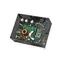
DM330023 Microchip Technology, DM330023 Datasheet - Page 25

DM330023
Manufacturer Part Number
DM330023
Description
BOARD DEV DSPICDEM MCHV
Manufacturer
Microchip Technology
Series
dsPICDEM™r
Datasheet
1.DM330023.pdf
(64 pages)
Specifications of DM330023
Main Purpose
Power Management, Motor Control
Embedded
Yes, Other
Utilized Ic / Part
dsPIC33F
Primary Attributes
AC Induction (ACIM) Motors, Brushless DC (BLDC) Motors, Permanent Magnet Synchronous (PMSM) Motors
Secondary Attributes
Power Factor Corrected (PFC)
Processor To Be Evaluated
dsPICDEM
Processor Series
dsPIC DSC
Interface Type
RS-232, USB
Operating Supply Voltage
90 V to 265 V
Lead Free Status / RoHS Status
Lead free / RoHS Compliant
Lead Free Status / RoHS Status
Lead free / RoHS Compliant, Lead free / RoHS Compliant
Available stocks
Company
Part Number
Manufacturer
Quantity
Price
Company:
Part Number:
DM330023
Manufacturer:
Microchip Technology
Quantity:
135
Company:
Part Number:
DM330023-2
Manufacturer:
MICROCHIP
Quantity:
12 000
2.4
2009 Microchip Technology Inc.
POWER SEQUENCES
The user should ensure that the following power sequences are adhered to.
2.4.1
The unit is powered-up when the power cable is connected to the AC mains. To verify
that the unit is powered make sure that the LEDs D6, D13, D17 and D18 are ON.
2.4.2
1. Stop firing all power devices by removing the PWM OUTPUTS shunt jumper.
2. Turn OFF the incoming AC supply by disconnecting the power cord from the
3. Wait until the red DC bus LED indicator (D13) located next to the DC bus P
2.4.3
The MPLAB Starter Kit Programmer/Debugger for the dsPICDEM™ MCHV Develop-
ment System may be used with MPLAB IDE, the free integrated development environ-
ment, which is available from Microchip’s web site (www.microchip.com). MPLAB IDE
allows the Starter Kit to be used as an in-circuit debugger as well as a programmer for
the following devices.
• dsPIC33FJ12MC202
• dsPIC33FJ32MC204
• dsPIC33FJ128MC804
• dsPIC33FJ256MC710
In-circuit debugging allows you to run, examine and modify your program for the device
embedded in the Starter Kit hardware. This greatly assists you in debugging your
firmware and hardware together.
Special Starter Kit software interacts with the MPLAB IDE application to run, stop, and
single-step through programs. Breakpoints can be set and the processor can be reset.
Once the processor is stopped, the register’s contents can be examined and modified.
For more information on how to use MPLAB IDE, reference the following
documentation:
• “MPLAB IDE User’s Guide” (DS51519)
• “MPLAB IDE Quick Start Guide” (DS51281)
• MPLAB IDE Online Help
2.4.4
To prepare the application for debug:
1. Launch MPLAB IDE, and then open the application project. The related work-
2. Select Project>Build All to build the application code. The build’s progress will be
Note:
mains.
connector has gone out (this will take 5 minutes or less).
space will be open. For information on projects and workspaces, see the MPLAB
IDE documentation mentioned at the beginning of this chapter.
visible in the Build tab of the Output window.
Power-up Sequence
Power-down Sequence
Programming/Debugging an Application Code Using the
Built-in Starter Kit Programmer/Debugger
Setting Up an Application for Debug
The unit is designed to be connected to the AC mains supply via a standard
non-locking plug. As the unit has no mains switch, this plug constitutes the
means of disconnection from the supply and thus the user must have
unobstructed access to this plug during operation.
DS70605A-page 19


