DM330023 Microchip Technology, DM330023 Datasheet - Page 44
DM330023
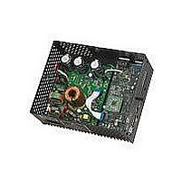
Manufacturer Part Number
DM330023
Description
BOARD DEV DSPICDEM MCHV
Manufacturer
Microchip Technology
Series
dsPICDEM™r
Datasheet
1.DM330023.pdf
(64 pages)
Specifications of DM330023
Main Purpose
Power Management, Motor Control
Embedded
Yes, Other
Utilized Ic / Part
dsPIC33F
Primary Attributes
AC Induction (ACIM) Motors, Brushless DC (BLDC) Motors, Permanent Magnet Synchronous (PMSM) Motors
Secondary Attributes
Power Factor Corrected (PFC)
Processor To Be Evaluated
dsPICDEM
Processor Series
dsPIC DSC
Interface Type
RS-232, USB
Operating Supply Voltage
90 V to 265 V
Lead Free Status / RoHS Status
Lead free / RoHS Compliant
Lead Free Status / RoHS Status
Lead free / RoHS Compliant, Lead free / RoHS Compliant
Available stocks
Company
Part Number
Manufacturer
Quantity
Price
Company:

Part Number:
DM330023
Manufacturer:
Microchip Technology
Quantity:
135
Company:
Part Number:
DM330023-2
Manufacturer:
MICROCHIP
Quantity:
12 000


dsPICDEM™ MCHV Development System User’s Guide
DS70605A-page 38
4.2.4
The Power Module Stage provides three different methods to sense the motor position.
These signals are also useful to determine the speed, the torque, current consumption
and the applied voltage.
Hall Sensors, the hall sensors circuitry is designed to attach open-collector configured
sensors. It has a pull-up resistor at the hall sensor inputs (R23, R24, and R25) and a
voltage divider (R26-R29, R27-R30, R28-R31) in order to scale the input waveforms to
the dsPIC DSC logic levels. C25-C27 and R26-R28 form a low-pass RC filter for each
hall sensor signal.
Phase Voltage Feedback circuitry for each phase is compounded by a voltage divider,
a current limiter and a low-pass RC filter. R79, R84 and R92 scale the phase M1 volt-
age in order to match the dsPIC DSC logic levels. R85 limits the current going to the
ADC pin (< 6mA). C51, R79 and R84 form the low-pass filter. The phase M2 and M3
has the exact same circuitry as shown in the schematic.
DC Bus Voltage Feedback is compounded by a voltage divider and a low-pass RC
filter. R75, R76 and R81 scale the DC bus voltage in order to match the dsPIC DSC
logic levels. C47, R75 and R76 form the low-pass filter.
Inverter Leg Shunt Resistor Feedback, a shunt resistor is located between the emit-
ter of the low side switches M1 and M2 and the “-DC bus”. A simple differential amplifier
circuit is used as shown in Appendix A. The operation of the circuit used for the M1
phase leg is described below:
The current is measured using the shunt resistor R86 and the operational amplifier
MCP6024 (U13A); R32, R33, R34, R36, R37 and R38 set the gain. R38 shifts the volt-
age present at the shunt resistor to a 1.65V DC level. Hence the voltage applied to the
dsPIC DSC ADC channel varies within 0-3.3V. The offset is controlled by R59, R60,
R38 and U13D. R35 and C34 filter out the high-frequency noise.
The same topology is used for the phase M2.
DC Bus Current Feedback, a shunt resistor is located between the shunt resistors of
side switches M1 and M2 and the “-DC bus”. A simple differential amplifier circuit is
used as shown in the schematic. The operation of the circuit used for sensing the DC
bus current is described as follows:
Note:
The current is sensed using the shunt resistor R95 and the operational amplifier
MCP6024 (U13C); R51, R52 and R49 set the gain. R58 shifts the voltage present
at the shunt resistor to a 1.65V DC level. Hence the voltage applied to the dsPIC
DSC ADC channel varies within 0-3.3V. The offset is controlled by R59, R60, R58
and U13D. R54 and C42 filter out the high-frequency noise.
Feedback Circuitry
It is possible to select any of these feedback signals using jumpers J12, J13
and J14, please refer to Section 4.2.8 “User Interfaces” for more
information.
2009 Microchip Technology Inc.
Related parts for DM330023
Image
Part Number
Description
Manufacturer
Datasheet
Request
R

Part Number:
Description:
Manufacturer:
Microchip Technology Inc.
Datasheet:
Part Number:
Description:
Manufacturer:
Microchip Technology Inc.
Datasheet:
Part Number:
Description:
Manufacturer:
Microchip Technology Inc.
Datasheet:
Part Number:
Description:
Manufacturer:
Microchip Technology Inc.
Datasheet:
Part Number:
Description:
Manufacturer:
Microchip Technology Inc.
Datasheet:
Part Number:
Description:
Manufacturer:
Microchip Technology Inc.
Datasheet:
Part Number:
Description:
Manufacturer:
Microchip Technology Inc.
Datasheet:
Part Number:
Description:
Manufacturer:
Microchip Technology Inc.
Datasheet: