DM330023 Microchip Technology, DM330023 Datasheet - Page 43
DM330023
Manufacturer Part Number
DM330023
Description
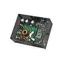
BOARD DEV DSPICDEM MCHV
Manufacturer
Microchip Technology
Series
dsPICDEM™r
Datasheet
1.DM330023.pdf
(64 pages)
Specifications of DM330023
Main Purpose
Power Management, Motor Control
Embedded
Yes, Other
Utilized Ic / Part
dsPIC33F
Primary Attributes
AC Induction (ACIM) Motors, Brushless DC (BLDC) Motors, Permanent Magnet Synchronous (PMSM) Motors
Secondary Attributes
Power Factor Corrected (PFC)
Processor To Be Evaluated
dsPICDEM
Processor Series
dsPIC DSC
Interface Type
RS-232, USB
Operating Supply Voltage
90 V to 265 V
Lead Free Status / RoHS Status
Lead free / RoHS Compliant
Lead Free Status / RoHS Status
Lead free / RoHS Compliant, Lead free / RoHS Compliant
Available stocks
Company
Part Number
Manufacturer
Quantity
Price
Company:

Part Number:
DM330023
Manufacturer:
Microchip Technology
Quantity:
135
Company:
Part Number:
DM330023-2
Manufacturer:
MICROCHIP
Quantity:
12 000


2009 Microchip Technology Inc.
4.2.2
The system default configuration is to get the 15V, 3.3V and 3.3V analog rail voltages
from the PFC stage board. However, it is also possible to use an external 24V power
supply to generate these voltages.
U19, C70, C73, C71 and C74 regulate the voltage applied to the system via J15 (28V
max). The output of the regulator is connected to the system through R109. The circuit
is shown in Appendix A. “Board Layout and Schematics”.
U18, C67, R110, C68, D16, D15, L3, R111, R112 and C75 regulate the 15 volts to cre-
ate a 3.3V digital rail. This auxiliary 3.3V digital rail is applied to the system through
R106. The circuit is shown in Appendix A. “Board Layout and Schematics”.
R114, R107, C69, and C72 form a decoupling circuit for generating a 3.3V rail for the
analog circuitry such as the ADC reference and the current feedback reference. This
auxiliary 3.3V analog rail is applied to the system through R108.
4.2.3
The three-phase inverter is embedded in a power module (U16). This power module
contains:
• 600V/30A 3-phase IGBT Inverter Bridge
• Gate driver circuitry for each IGBT
• Three Independent connections to the negative DC bus for current sensing
• Short-circuit protection circuitry
• Thermal Shutdown
• Gate Driver Power Supply Undervoltage protection
• Gate Driver Power Supply Overvoltage protection
• Single-grounded power supply
• Isolation of 2.5 kV per minute
• Maximum switching frequency: 20 kHz
The dsPIC DSC provides the PWM signals to this power module in order to turn on/off
the IGBT, and therefore apply power to the motor phases.
R95 sets the threshold limit for the overcurrent circuitry. If this voltage is greater than
0.5 V (typical), a fault signal is asserted and the low-side IGTBs are turned off. R94 and
C53 form a low-pass RC filter that filters out the frequencies above 88.4 kHz.
C56 sets the fault pulse duration, the value of C56 is given by the following equation:
C56 = 18.3E-6 x 1.8E-3 seconds. Therefore, the fault pulse duration is 54 µs
The power module fault output pin (VFO) is open-collector configured. R50 pulls up the
fault output to the analog 3.3V rail. R53 and C40 form a low-pass RC filter that filters
out the frequencies above 53 kHz.
For more information about this power module please refer to the manufacturer’s data
sheet.
Note:
Note:
Note:
Power Supplies
Power Module
It is the responsibility of the user to populate these components if an
external power supply is used.
It is the responsibility of the user to populate these components if an
external power supply is used.
It is the responsibility of the user to populate these components if an
external power supply is used.
DS70605A-page 37
Related parts for DM330023
Image
Part Number
Description
Manufacturer
Datasheet
Request
R

Part Number:
Description:
Manufacturer:
Microchip Technology Inc.
Datasheet:
Part Number:
Description:
Manufacturer:
Microchip Technology Inc.
Datasheet:
Part Number:
Description:
Manufacturer:
Microchip Technology Inc.
Datasheet:
Part Number:
Description:
Manufacturer:
Microchip Technology Inc.
Datasheet:
Part Number:
Description:
Manufacturer:
Microchip Technology Inc.
Datasheet:
Part Number:
Description:
Manufacturer:
Microchip Technology Inc.
Datasheet:
Part Number:
Description:
Manufacturer:
Microchip Technology Inc.
Datasheet:
Part Number:
Description:
Manufacturer:
Microchip Technology Inc.
Datasheet: