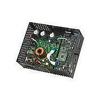
DM330023 Microchip Technology, DM330023 Datasheet - Page 37

DM330023
Manufacturer Part Number
DM330023
Description
BOARD DEV DSPICDEM MCHV
Manufacturer
Microchip Technology
Series
dsPICDEM™r
Datasheet
1.DM330023.pdf
(64 pages)
Specifications of DM330023
Main Purpose
Power Management, Motor Control
Embedded
Yes, Other
Utilized Ic / Part
dsPIC33F
Primary Attributes
AC Induction (ACIM) Motors, Brushless DC (BLDC) Motors, Permanent Magnet Synchronous (PMSM) Motors
Secondary Attributes
Power Factor Corrected (PFC)
Processor To Be Evaluated
dsPICDEM
Processor Series
dsPIC DSC
Interface Type
RS-232, USB
Operating Supply Voltage
90 V to 265 V
Lead Free Status / RoHS Status
Lead free / RoHS Compliant
Lead Free Status / RoHS Status
Lead free / RoHS Compliant, Lead free / RoHS Compliant
Available stocks
Company
Part Number
Manufacturer
Quantity
Price
Company:
Part Number:
DM330023
Manufacturer:
Microchip Technology
Quantity:
135
Company:
Part Number:
DM330023-2
Manufacturer:
MICROCHIP
Quantity:
12 000
2009 Microchip Technology Inc.
4.1.3
In a DSC-based PFC, the relevant analog parameters and the control loops need to be
redefined and discretized. This enables changeover from existing hardware to its digital
counterpart easier and more logical.
The PFC is an AC-to-DC converter, which converts the AC input voltage to a DC volt-
age and maintains sinusoidal input current at a high input power factor. In a DSC-based
PFC, three inputs signals are required to implement the current control.
The input rectifier (BR1) converts (shown in Section 4.1.1 “AC Supply Input ”) the
alternating voltage at power frequency into unidirectional voltage. This rectified voltage
is fed to the chopper circuit to produce a smooth and constant DC output voltage to the
load. The chopper circuit is controlled by the PWM switching pulses generated by the
dsPIC DSC device, based on three measured feedback signals:
• Rectified input voltage
• AC input voltage zero-crossing event
• Rectified input current
• DC bus voltage
The rectified input voltage is measured in two stages:
• Signal conditioning: R22, R23, R24, C24, and D7 convert and filter the AC input
• Amplification: the operational amplifier MCP6024 (U13B) amplifies the condi-
AC input voltage zero-crossing event is sensed using a voltage divider (R2-R5) and two
opto-couplers (U1 and U2). The circuit is shown in Appendix A.
Rectified input current is measured using the shunt resistor R34 and the operational
amplifier MCP6024 (U13A); R38, R39, R40, R41, R42 and R43 set the gain. R43 shifts
the voltage present at the shunt resistor to a 1.65V DC level. Therefore, the voltage
applied to the dsPIC DSC ADC channel varies within 0-3.3V. The offset is controlled by
R43, R53, and R54. R44 and C37 filter out the high-frequency noise. The circuit is
shown in Appendix A.
DC bus voltage, the DC bus voltage is sensed at the power module stage. Please refer
to Section 4.2.4 “Feedback Circuitry”.
4.1.4
The PFC stage board provides the 15 volts power supply required to fire the power
module IGBTs. The 15 volts power supply is built using a low power off-line SMPS pri-
mary switcher. The switching frequency is fixed to 60 kHz, the feedback signal to the
power supply is provided by and opto-coupler. The output voltage is regulated at 15V
with a maximum output current of 0.750 A, the resultant maximum power is 11.25 W.
The input voltage range for this power supply is from 90 VAC to 260 VAC.
The PFC stage board also provides the 3.3 volts to powering-up the dsPIC DSC, the
isolation circuitry, the communication ports, the Starter Kit programmer, etc. It also gen-
erates the 3.3 volts for powering the analog circuits and the analog reference for the
Analog-To-Digital converter.
voltage waveform from 90-265 VAC to 0-3.3 VAC. D7 limit the maximum voltage
to 3.3V. C24 along with R22, R23 form a low-pass filter. The circuit is shown in
Appendix A.
tioned AC input voltage; R45, R46, R47, R48, R49 and R51 set the gain. The
MC6024 also shifts the conditioned AC input voltage to a 1.65V DC level. There-
fore, the voltage applied to the dsPIC DSC ADC channel varies within 0-3.3V. The
offset is controlled by R50, R53, and R54. R39 and C39 filter out the
high-frequency noise.
PFC Feedback Circuitry
Power Supplies
DS70605A-page 31


