STEVAL-IPE008V1 STMicroelectronics, STEVAL-IPE008V1 Datasheet - Page 22
STEVAL-IPE008V1
Manufacturer Part Number
STEVAL-IPE008V1
Description
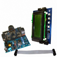
BOARD EVAL STPM01/STR715FR0
Manufacturer
STMicroelectronics
Type
Other Power Managementr
Specifications of STEVAL-IPE008V1
Main Purpose
Power Management, Energy/Power Meter
Embedded
Yes, MCU, ARM7
Utilized Ic / Part
STPM01, STR715FR0
Primary Attributes
3-Ph Energy Meter (or Single Phase)
Secondary Attributes
Measures Active, Reactive, Apparent Power
Product
Power Management Modules
Lead Free Status / RoHS Status
Lead free / RoHS Compliant
For Use With/related Products
STPM01, STR715FR0
Other names
497-6412
STEVAL-IPE008V1
STEVAL-IPE008V1


Theory of operation
Table 10.
8.7
22/60
for tampering purposes or in case the line voltage is very stable, it is possible to use a
predefined value for computing the energy without sensing it.
In order to enable the SWM mode, the STPM01 must be configured with PST values of 4 or
5, (tamper enabled-Rogowsky coils). In this way, if the BFR error is detected, STPM01
enters in SWM. If BFR is cleared the energy calculation is performed normally, when BFR is
set (no voltage information is available) the energy computation is carried out using a
nominal voltage value according to the NOM configuration bits.
Since there is no more information on the phase shift between voltage and current, the
apparent rather than active power is used for tamper and energy computation. The
calculated apparent energy is the product between I
equivalent V
V
where V
coefficient that changes according to the following table:
Nominal voltage values
For example, if a R
voltage is present, the positive voltage present at the input of the voltage channel of
STPM01 is:
since the maximum voltage value applicable to the voltage channel input of STPM01 is +0.3
V, the equivalent maximum line voltage applicable is:
V
considering the case of NOM=2, the correspondent RMS values used for energy
computation are:
V
Usually the supply voltage for the electronic meter is taken from the line voltage, in SWM,
since the line voltage is not present any more, some other power source must be used in
order to provide the necessary supply to STPM01 and the other electronic components of
the meter.
Power supply
The main STPM01 supply pin is the V
the necessary voltage for the analog part V
The V
VI
RMS
PK
RMS
=
= R
R
= V
SS
= V
1
R
1
+
PK
pin represents the reference point for all the internal signals. 100 nF low ESR
+R
2
PK
PK
R
NOM
represents the maximum line voltage reading of the STPM01 and K
2
*K
0
1
2
3
2
RMS
• 0.4219 = 208.76 [V]
/R
⋅
NOM
V
2
RMS
that can be calculated as follows:
• 0.3 = 494.82
,
1
= 783 kΩ and R
2
Doc ID 10853 Rev 7
2
CC
= 475 Ω are used as resistor divider when the line
pin. From the V
DDA
(3 V) and for the digital part V
RMS
CC
(effectively measured) and an
pin two linear regulators provide
0.3594
0.3906
0.4219
0.4531
K
NOM
DDD
NOM
(1.5 V).
STPM01
is a
Related parts for STEVAL-IPE008V1
Image
Part Number
Description
Manufacturer
Datasheet
Request
R

Part Number:
Description:
BOARD DEMO TFT DISPLAY STR91
Manufacturer:
STMicroelectronics
Datasheet:

Part Number:
Description:
BOARD EVAL FOR MEMS SENSORS
Manufacturer:
STMicroelectronics
Datasheet:

Part Number:
Description:
KIT DEV STARTER ST10F276Z5
Manufacturer:
STMicroelectronics
Datasheet:

Part Number:
Description:
BOARD EVAL HDMI $ VIDEO SWITCH
Manufacturer:
STMicroelectronics
Datasheet:

Part Number:
Description:
BOARD DEMO ACCELEROMETER DIL24
Manufacturer:
STMicroelectronics
Datasheet:

Part Number:
Description:
BOARD STLM75/STDS75/ST72F651
Manufacturer:
STMicroelectronics
Datasheet:

Part Number:
Description:
EVAL BOARD 3AXIS MEMS ACCELLRMTR
Manufacturer:
STMicroelectronics
Datasheet:

Part Number:
Description:
BOARD EVAL 8BIT MICRO + TDE1708
Manufacturer:
STMicroelectronics
Datasheet:

Part Number:
Description:
EVAL BOARD A/D TS4657
Manufacturer:
STMicroelectronics
Datasheet:

Part Number:
Description:
BOARD ADAPTER 20DIP LIS3LV02DL
Manufacturer:
STMicroelectronics
Datasheet:
Part Number:
Description:
STMicroelectronics [RIPPLE-CARRY BINARY COUNTER/DIVIDERS]
Manufacturer:
STMicroelectronics
Datasheet:
Part Number:
Description:
STMicroelectronics [LIQUID-CRYSTAL DISPLAY DRIVERS]
Manufacturer:
STMicroelectronics
Datasheet:
Part Number:
Description:
BOARD EVAL FOR MEMS SENSORS
Manufacturer:
STMicroelectronics
Datasheet: