STEVAL-IPE008V1 STMicroelectronics, STEVAL-IPE008V1 Datasheet - Page 38
STEVAL-IPE008V1
Manufacturer Part Number
STEVAL-IPE008V1
Description
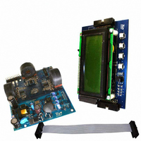
BOARD EVAL STPM01/STR715FR0
Manufacturer
STMicroelectronics
Type
Other Power Managementr
Specifications of STEVAL-IPE008V1
Main Purpose
Power Management, Energy/Power Meter
Embedded
Yes, MCU, ARM7
Utilized Ic / Part
STPM01, STR715FR0
Primary Attributes
3-Ph Energy Meter (or Single Phase)
Secondary Attributes
Measures Active, Reactive, Apparent Power
Product
Power Management Modules
Lead Free Status / RoHS Status
Lead free / RoHS Compliant
For Use With/related Products
STPM01, STR715FR0
Other names
497-6412
STEVAL-IPE008V1
STEVAL-IPE008V1


Theory of operation
Table 17.
38/60
Bit #
0
1
2
3
4
5
6
7
Precharge
Reserved
Reserved
Signal
PUMP
BANK
name
CSEL
WE
RD
Mode signals description
– RD mode signal has been already described in the SPI section but there is another
– PUMP: when set, the PUMP mode signal transform the MOP and MON pins to act as
– CSEL In normal operation, if the anti-tamper module is not activated (see PST
– WE (write enable): This mode signal is used to permanently write to the OTP antifuse
– Precharge: this command swaps the sequence of data record read, allowing the
value
Bit
implied function of the signal RD. When it is set, each sense amplifier is disconnected
from corresponding antifuse element and this way, its 3 V NMOS gate is protected
from the high voltage of VOTP during permanent write operation. This means that as
long as the VOTP voltage reads more than 3 V, the signal RD should be set.
driving signals to implement a charge-pump DC-DC converter (see schematic page
36). This feature is useful in order to boost the V
generate the VOTP voltage (14 V to 20 V) needed to program the OTP antifuse
elements.
configuration bits) the STPM01 will select the channel 1 as source of current
information. For debug or calibration purposes it is possible to select channel 2 as
source of current channel signal when the tamper module is disabled. This is done
setting CSEL mode bit.
element. When this bit is not set, any write to the configuration bit is recorded in the
shadow latches. When this bit is set the writing is recorded both in the shadow latch
and in the OTP antifuse element.
reading of the last four data records as first and the first four as second. The reading
sequence will be 5, 6, 7, 8, 1, 2, 3, 4. Differently from the other mode signals, the
precharge command is not retained inside the STPM01, in fact it should be sent each
time before the reading of the data records. This is the only command that can be
sent to STPM01 when the TSTD bit has been set.
0
1
0
1
0
1
0
1
0
1
1
Used for RC startup procedure
MOP and MON operates normally
MOP and MON provides the driving signals to implement a
charge-pump DC-DC converter
Current Channel 1 selected when tamper is disabled
Channel 2 selected when tamper is disabled
The 56 Configuration bits originated by OTP antifuses
The 56 Configuration bits originated by shadow latches
Any writing in the configuration bits is recorded in the
shadow latches
Any writing in the configuration bits is recorded both in the
shadow latches and in the OTP antifuse elements
Swap the 32 bits data records reading. From
1,2,3,4,5,6,7,8, to 5,6,7,8,1,2,3,4 and viceversa
Doc ID 10853 Rev 7
Status
CC
supply voltage of the STPM01 to
command
0111100x
0111000x
1111000x
0111001x
1111001x
1111100x
0111101x
1111101x
0111110x
1111110x
1111111x
Binary
command
FC or FD
7C or 7D
7A or 7B
FA or FB
F0 or F1
F2 or F3
F8 or F9
70 or 71
72 or 73
78 or 79
Hex
STPM01
FF
Related parts for STEVAL-IPE008V1
Image
Part Number
Description
Manufacturer
Datasheet
Request
R

Part Number:
Description:
BOARD DEMO TFT DISPLAY STR91
Manufacturer:
STMicroelectronics
Datasheet:

Part Number:
Description:
BOARD EVAL FOR MEMS SENSORS
Manufacturer:
STMicroelectronics
Datasheet:

Part Number:
Description:
KIT DEV STARTER ST10F276Z5
Manufacturer:
STMicroelectronics
Datasheet:

Part Number:
Description:
BOARD EVAL HDMI $ VIDEO SWITCH
Manufacturer:
STMicroelectronics
Datasheet:

Part Number:
Description:
BOARD DEMO ACCELEROMETER DIL24
Manufacturer:
STMicroelectronics
Datasheet:

Part Number:
Description:
BOARD STLM75/STDS75/ST72F651
Manufacturer:
STMicroelectronics
Datasheet:

Part Number:
Description:
EVAL BOARD 3AXIS MEMS ACCELLRMTR
Manufacturer:
STMicroelectronics
Datasheet:

Part Number:
Description:
BOARD EVAL 8BIT MICRO + TDE1708
Manufacturer:
STMicroelectronics
Datasheet:

Part Number:
Description:
EVAL BOARD A/D TS4657
Manufacturer:
STMicroelectronics
Datasheet:

Part Number:
Description:
BOARD ADAPTER 20DIP LIS3LV02DL
Manufacturer:
STMicroelectronics
Datasheet:
Part Number:
Description:
STMicroelectronics [RIPPLE-CARRY BINARY COUNTER/DIVIDERS]
Manufacturer:
STMicroelectronics
Datasheet:
Part Number:
Description:
STMicroelectronics [LIQUID-CRYSTAL DISPLAY DRIVERS]
Manufacturer:
STMicroelectronics
Datasheet:
Part Number:
Description:
BOARD EVAL FOR MEMS SENSORS
Manufacturer:
STMicroelectronics
Datasheet: