STEVAL-IPE008V1 STMicroelectronics, STEVAL-IPE008V1 Datasheet - Page 32
STEVAL-IPE008V1
Manufacturer Part Number
STEVAL-IPE008V1
Description
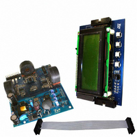
BOARD EVAL STPM01/STR715FR0
Manufacturer
STMicroelectronics
Type
Other Power Managementr
Specifications of STEVAL-IPE008V1
Main Purpose
Power Management, Energy/Power Meter
Embedded
Yes, MCU, ARM7
Utilized Ic / Part
STPM01, STR715FR0
Primary Attributes
3-Ph Energy Meter (or Single Phase)
Secondary Attributes
Measures Active, Reactive, Apparent Power
Product
Power Management Modules
Lead Free Status / RoHS Status
Lead free / RoHS Compliant
For Use With/related Products
STPM01, STR715FR0
Other names
497-6412
STEVAL-IPE008V1
STEVAL-IPE008V1


Theory of operation
Table 15.
8.18
32/60
Bit #
0
1
2
3
4
5
6
7
Name
MUX
BCF
BFR
HLT
PIN
BIL
BIT
LIN
Status bit description
When STPM01 is used in peripheral mode all these signal can be read through the SPI
interface. See paragraph 16 for details on the Status bit location in the STPM01 data
records.
In standalone mode the BIL signal is available in SCLNLC pin and the BIT signal in the
SDATD pin. All the other signals can be read only through SPI interface.
Programming the STPM01
Data records
The STPM01 has 8 internal data records registers. Every data record consists of 4-bit parity
code and 28-bit data value where the parity code is computed from the data value, which
makes total of 32 bits or 4 bytes.
The figure below shows the data records structure with the name of the contained
information.
Each bit of parity nibble is defined as odd parity of all seven corresponding bits of data
nibbles.
No load condition
∑ Δ signals status
Line frequency range
Tamper condition
Current channel selection
Trend of the line voltage
Output pins check
Data Validity
Description
BIL=0: No load condition not detected
BIL=1: No load detected
BCF=0: ∑ Δ signals alive
BCF=1: one or both ∑ Δ signals are stacked
BFR=0: Line frequency inside the 45Hz-65Hz range
BFR=1: Line frequency out of range
BIT=0: Tamper not detected;
BIT=1: Tamper detected;
MUX=0: Primary current channels selected by the tamper module;
MUX=1: Secondary current channels selected by the tamper
module;
LIN=0: line voltage is going from the minimum to the maximum value.
(Δv/Δt >0);
LIN=1: line voltage is going from the maximum to the minimum value.
(Δv/Δt < 0);
PIN=0: the output pins are consistent with the data
PIN=1: the output pins are different with the data, this means some
output pin is forced to 1 or 0.
HLT=0: the data records reading are valid.
HLT=1: the data records are not valid. A reset occurred and a restart
is in progress.
Doc ID 10853 Rev 7
Condition
STPM01
Related parts for STEVAL-IPE008V1
Image
Part Number
Description
Manufacturer
Datasheet
Request
R

Part Number:
Description:
BOARD DEMO TFT DISPLAY STR91
Manufacturer:
STMicroelectronics
Datasheet:

Part Number:
Description:
BOARD EVAL FOR MEMS SENSORS
Manufacturer:
STMicroelectronics
Datasheet:

Part Number:
Description:
KIT DEV STARTER ST10F276Z5
Manufacturer:
STMicroelectronics
Datasheet:

Part Number:
Description:
BOARD EVAL HDMI $ VIDEO SWITCH
Manufacturer:
STMicroelectronics
Datasheet:

Part Number:
Description:
BOARD DEMO ACCELEROMETER DIL24
Manufacturer:
STMicroelectronics
Datasheet:

Part Number:
Description:
BOARD STLM75/STDS75/ST72F651
Manufacturer:
STMicroelectronics
Datasheet:

Part Number:
Description:
EVAL BOARD 3AXIS MEMS ACCELLRMTR
Manufacturer:
STMicroelectronics
Datasheet:

Part Number:
Description:
BOARD EVAL 8BIT MICRO + TDE1708
Manufacturer:
STMicroelectronics
Datasheet:

Part Number:
Description:
EVAL BOARD A/D TS4657
Manufacturer:
STMicroelectronics
Datasheet:

Part Number:
Description:
BOARD ADAPTER 20DIP LIS3LV02DL
Manufacturer:
STMicroelectronics
Datasheet:
Part Number:
Description:
STMicroelectronics [RIPPLE-CARRY BINARY COUNTER/DIVIDERS]
Manufacturer:
STMicroelectronics
Datasheet:
Part Number:
Description:
STMicroelectronics [LIQUID-CRYSTAL DISPLAY DRIVERS]
Manufacturer:
STMicroelectronics
Datasheet:
Part Number:
Description:
BOARD EVAL FOR MEMS SENSORS
Manufacturer:
STMicroelectronics
Datasheet: