STEVAL-IPE008V1 STMicroelectronics, STEVAL-IPE008V1 Datasheet - Page 26
STEVAL-IPE008V1
Manufacturer Part Number
STEVAL-IPE008V1
Description
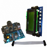
BOARD EVAL STPM01/STR715FR0
Manufacturer
STMicroelectronics
Type
Other Power Managementr
Specifications of STEVAL-IPE008V1
Main Purpose
Power Management, Energy/Power Meter
Embedded
Yes, MCU, ARM7
Utilized Ic / Part
STPM01, STR715FR0
Primary Attributes
3-Ph Energy Meter (or Single Phase)
Secondary Attributes
Measures Active, Reactive, Apparent Power
Product
Power Management Modules
Lead Free Status / RoHS Status
Lead free / RoHS Compliant
For Use With/related Products
STPM01, STR715FR0
Other names
497-6412
STEVAL-IPE008V1
STEVAL-IPE008V1


Theory of operation
8.11
8.12
26/60
samples, called B and A respectively, the criteria of tamper is calculated and the channel
with higher current is selected, resulting in a new tamper state. If four consecutive new
results of criteria happen, i.e. after elapsed 5.12 s at 50 Hz, the meter will enter into tamper
state. Thus, the channel with the higher current will be selected for the energy calculation. If
samples of power A and B would have different signs, the Tamper would be on all the time
but, the channel with bigger power would be still selected for the final integration of energy.
If a tamper status has been detected, the multiplex ratio will be 56:8 if the primary channel
energy is greater than the secondary one, otherwise it will be 8:56.
The detected tamper condition is stored in the BIT status bit. If BIT = 0 tamper is not
detected, if BIT = 1 a tamper condition has been detected. In standalone mode the BIT flag
is also available in the SDATD pin.
Phase compensation
The STPM01 is does not introduce any phase shift between voltage and current channel.
However, the voltage and current signals come from transducers, which could have inherent
phase errors. For example, a phase error of 0.1° to 0.3° is not uncommon for a current
transformer (CT). These phase errors can vary from part to part, and they must be corrected
in order to perform accurate power calculations. The errors associated with phase mismatch
are particularly noticeable at low power factors. The STPM01 provides a means of digitally
calibrating these small phase errors through a introducing delays on the voltage or current
signal. The amount of phase compensation can be set using the 4 bits of the phase
calibration register (CPH).
The default value of this register is at value of 0 which gives 0° phase compensation. When
the 4 bits give a CPH of 15 (1111) the introduced compensation is +0.576°. This
compensates the phase shift usually introduced by the current sensor, while the voltage
sensor, normally a resistor divider, does not introduce any delay. The resolution step of the
phase compensation is 0.038°.
Clock generator
All the internal timing of the STPM01 is based on the CLKOUT signal. This signal can be
generated in three different ways:
1.
2.
3.
The clock generator is powered from analog supply and is responsible for two tasks. The
first one is to retard the turn on of some function blocks after POR in order to help smooth
start of external power supply circuitry by keeping off all major loads.
The second task of the clock generator is to provide all necessary clocks for analog and
digital parts. Within this task, the MDIV configuration bit is used to inform the device about
RC: this oscillator mode can be selected using the RC configuration bit. If RC = 1 the
STPM01 will run using the RC oscillator. A resistor connected between CLKIN and
ground will set the RC current. For 4 MHz operation the suggested settling resistor is
12 kΩ; The oscillator frequency can be compensated using the CRC configuration bit
(see
Quartz: If RC = 0 the oscillator will work with an external crystal. The suggested circuit
is depicted in
External clock: keeping RC=0, it is also possible to feed the CLKOUT pin with an
external oscillator signal
Table
16)
Figure
20;
Doc ID 10853 Rev 7
STPM01
Related parts for STEVAL-IPE008V1
Image
Part Number
Description
Manufacturer
Datasheet
Request
R

Part Number:
Description:
BOARD DEMO TFT DISPLAY STR91
Manufacturer:
STMicroelectronics
Datasheet:

Part Number:
Description:
BOARD EVAL FOR MEMS SENSORS
Manufacturer:
STMicroelectronics
Datasheet:

Part Number:
Description:
KIT DEV STARTER ST10F276Z5
Manufacturer:
STMicroelectronics
Datasheet:

Part Number:
Description:
BOARD EVAL HDMI $ VIDEO SWITCH
Manufacturer:
STMicroelectronics
Datasheet:

Part Number:
Description:
BOARD DEMO ACCELEROMETER DIL24
Manufacturer:
STMicroelectronics
Datasheet:

Part Number:
Description:
BOARD STLM75/STDS75/ST72F651
Manufacturer:
STMicroelectronics
Datasheet:

Part Number:
Description:
EVAL BOARD 3AXIS MEMS ACCELLRMTR
Manufacturer:
STMicroelectronics
Datasheet:

Part Number:
Description:
BOARD EVAL 8BIT MICRO + TDE1708
Manufacturer:
STMicroelectronics
Datasheet:

Part Number:
Description:
EVAL BOARD A/D TS4657
Manufacturer:
STMicroelectronics
Datasheet:

Part Number:
Description:
BOARD ADAPTER 20DIP LIS3LV02DL
Manufacturer:
STMicroelectronics
Datasheet:
Part Number:
Description:
STMicroelectronics [RIPPLE-CARRY BINARY COUNTER/DIVIDERS]
Manufacturer:
STMicroelectronics
Datasheet:
Part Number:
Description:
STMicroelectronics [LIQUID-CRYSTAL DISPLAY DRIVERS]
Manufacturer:
STMicroelectronics
Datasheet:
Part Number:
Description:
BOARD EVAL FOR MEMS SENSORS
Manufacturer:
STMicroelectronics
Datasheet: