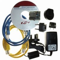
CP2201EK Silicon Laboratories Inc, CP2201EK Datasheet - Page 37

CP2201EK
Manufacturer Part Number
CP2201EK
Description
KIT EVAL FOR CP2201 ETH CTRLR
Manufacturer
Silicon Laboratories Inc
Type
Controllers & Processorsr
Specifications of CP2201EK
Main Purpose
Interface, Ethernet Sensor
Embedded
Yes, MCU, 8-Bit
Utilized Ic / Part
CP2200, CP2201
Primary Attributes
Temperature and Light Sensor
Secondary Attributes
Graphic User Interface
Interface Type
Ethernet
Product
Modules
Silicon Manufacturer
Silicon Labs
Silicon Core Number
CP2201
Silicon Family Name
CP220x
Kit Contents
CP2201 Evaluation Board, Power Adapter, CAT5e Ethernet Cable, CD-ROM, Quick-Start Guide
For Use With/related Products
CP2201
Lead Free Status / RoHS Status
Contains lead / RoHS non-compliant
Lead Free Status / RoHS Status
Lead free / RoHS Compliant, Contains lead / RoHS non-compliant
Other names
336-1316
Available stocks
Company
Part Number
Manufacturer
Quantity
Price
Company:
Part Number:
CP2201EK
Manufacturer:
SiliconL
Quantity:
8
9. Reset Sources
Reset circuitry allows the CP2200/1 to be easily placed in a predefined default condition. Upon entry to this reset
state, the following events occur:
The contents of the transmit and receive buffers are unaffected by a reset as long as the device has maintained
sufficient supply voltage. However, since the buffer pointers are reset to their default values, the data is effectively
lost unless the host processor has kept track of the starting address and length of each packet in the buffer.
The CP2200/1 has five reset sources that place the device in the reset state. The method of entry to the reset state
determines the amount of time spent in reset and the behavior of the /RST pin. Each of the following reset sources
is described in the following sections:
Upon exit from the reset state, the device automatically starts the external oscillator and waits for it to settle (this
step is skipped on software reset). Once the crystal oscillator settles, the Oscillator Initialization Complete interrupt
occurs (interrupt pin asserted), and the host processor may now access the internal registers to poll for the Self
Initialization Complete Interrupt. If the host does not have access to the interrupt signal, it should wait
approximately 1 ms after the rising edge of reset pin prior to polling the internal registers. Note that the reset pin
could remain low up to 100 ms depending on the power supply ramp time.
The device is fully functional after the Self Initialization has completed. See “6.2. Reset Initialization” on page 18 for
the recommended initialization procedure following a device reset.
All direct and indirect registers are initialized to their defined reset values.
Digital pins (except /RST) are forced into a high impedance state with a weak pull-up to V
Analog pins (TX+/TX–, RX+/RX–) are forced into a high impedance state without a weak pull-up.
The external oscillator is stopped and /RST driven low (except on a software reset).
All interrupts are enabled.
Power-On
Power-Fail
Oscillator-Fail
External /RST Pin
Software Command
Rev. 1.0
DD
CP2200/1
.
37


