MCP1640EV-SBC Microchip Technology, MCP1640EV-SBC Datasheet - Page 12
MCP1640EV-SBC
Manufacturer Part Number
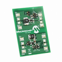
MCP1640EV-SBC
Description
BOARD EVAL FOR MCP1640
Manufacturer
Microchip Technology
Type
DC/DC Switching Converters, Regulators & Controllersr
Datasheets
1.MCP1640CT-ICHY.pdf
(32 pages)
2.MCP1640CT-ICHY.pdf
(26 pages)
3.MCP1640EV-SBC.pdf
(22 pages)
Specifications of MCP1640EV-SBC
Main Purpose
DC/DC, Step Up
Outputs And Type
1, Non-Isolated
Voltage - Output
2V, 3.3V or 5V
Current - Output
100mA, 350mA
Voltage - Input
0.35 ~ 5.5V
Regulator Topology
Boost
Frequency - Switching
500kHz
Board Type
Fully Populated
Utilized Ic / Part
MCP1640
Input Voltage
0.35 V to 5.5 V
Output Voltage
3.3 V to 5 V
Operating Supply Voltage
0.35 V to 5.5 V
Product
Power Management Modules
Supply Current
300 mA
Kit Contents
Board
Features
Automatic PFM/PWM Operation, Enable State Selectable Using Mini-Dip Switch On Board
Svhc
No SVHC (15-Dec-2010)
Core Architecture
Power Management - Voltage Regulator
Rohs Compliant
Yes
For Use With/related Products
MCP1640
Lead Free Status / RoHS Status
Contains lead / RoHS non-compliant
Power - Output
-
Lead Free Status / Rohs Status
Lead free / RoHS Compliant
Available stocks
Company
Part Number
Manufacturer
Quantity
Price
Company:

Part Number:
MCP1640EV-SBC
Manufacturer:
Microchip Technology
Quantity:
135
Company:
Part Number:
MCP1640EV-SBC
Manufacturer:
MICROCHIP
Quantity:
12 000


MCP1640/B/C/D
4.2
The MCP1640/B/C/D is a compact, high-efficiency,
fixed frequency, step-up DC-DC converter that
provides an easy-to-use power supply solution for
applications powered by either one-cell, two-cell, or
three-cell alkaline, NiCd, or NiMH, or one-cell Li-Ion or
Li-Polymer batteries.
FIGURE 4-1:
4.2.1
The MCP1640/B/C/D is capable of starting from a low
input voltage. Start-up voltage is typically 0.65V for a
3.3V output and 1 mA resistive load.
When enabled, the internal start-up logic turns the
rectifying P-Channel switch on until the output
capacitor is charged to a value close to the input
voltage. The rectifying switch is current limited during
this time. After charging the output capacitor to the
input voltage, the device starts switching. If the input
voltage is below 1.6V, the device runs open-loop with a
fixed duty cycle of 70% until the output reaches 1.6V.
During this time, the boost switch current is limited to
DS22234A-page 12
SW
EN
GND
Functional Description
V IN
LOW-VOLTAGE START-UP
MCP1640/B/C/D Block Diagram.
GATE DRIVE
SHUTDOWN
OSCILLATOR
CONTROL
INTERNAL
PWM/PFM
LOGIC
LOGIC
AND
BIAS
V OUT
.3V
0V
DIRECTION
CONTROL
SLOPE
COMP.
SOFT-START
Figure 4-1 depicts the functional block diagram of the
MCP1640/B/C/D.
50% of its nominal value. Once the output voltage
reaches 1.6V, normal closed-loop PWM operation is
initiated.
The MCP1640/B/C/D charges an internal capacitor
with a very weak current source. The voltage on this
capacitor, in turn, slowly ramps the current limit of the
boost switch to its nominal value. The soft-start
capacitor is completely discharged in the event of a
commanded shutdown or a thermal shutdown.
There is no undervoltage lockout feature for the
MCP1640/B/C/D. The device will start up at the lowest
possible voltage and run down to the lowest possible
voltage. For typical battery applications, this may result
in “motor-boating” for deeply discharged batteries.
EA
I
I LIMIT
I SENSE
ZERO
1.21V
2010 Microchip Technology Inc.
FB
Related parts for MCP1640EV-SBC
Image
Part Number
Description
Manufacturer
Datasheet
Request
R

Part Number:
Description:
0.65V Start-up Synchronous Boost Regulator with True Output Disconnect or Input/Output Bypass Option
Manufacturer:
MICROCHIP [Microchip Technology]
Datasheet:

Part Number:
Description:
IC CONV DC-DC STEPUP SYNC 8DFN
Manufacturer:
Microchip Technology
Datasheet:

Part Number:
Description:
0.65v Start-up Synchronous Boost Regulator With True Output Disconnect Or Input/output Bypass Option
Manufacturer:
Microchip Technology Inc.
Datasheet:
Part Number:
Description:
Manufacturer:
Microchip Technology Inc.
Datasheet:
Part Number:
Description:
Manufacturer:
Microchip Technology Inc.
Datasheet:
Part Number:
Description:
Manufacturer:
Microchip Technology Inc.
Datasheet:
Part Number:
Description:
Manufacturer:
Microchip Technology Inc.
Datasheet:
Part Number:
Description:
Manufacturer:
Microchip Technology Inc.
Datasheet:
Part Number:
Description:
Manufacturer:
Microchip Technology Inc.
Datasheet:
Part Number:
Description:
Manufacturer:
Microchip Technology Inc.
Datasheet: